Warning: preg_replace(): The /e modifier is deprecated, use preg_replace_callback instead in ..../includes/class_bbcode.php on line 2958

Warning: preg_replace(): The /e modifier is deprecated, use preg_replace_callback instead in ..../includes/class_bbcode.php on line 2968

Warning: preg_replace(): The /e modifier is deprecated, use preg_replace_callback instead in ..../includes/class_bbcode.php on line 2958
First attempts at self built pedal kits
Page 1 of 2 12 LastLast
Results 1 to 19 of 34

Thread: First attempts at self built pedal kits

  1. #1
    Join Date
    Sep 2007
    Location
    Clarksburg, WV
    Posts
    209
    Post Thanks / Like

    Default First attempts at self built pedal kits

    Hey guys. It's been forever since i've posted on here, but my tax return has been burning a hold in my bank account. Thus, I've decided to release a little of my gear GAS and up my set up a little bit. Which brings me to the two pedal kits i've ordered from GGG. I ordered the tremelo and tube screamer kit after having some success with soldering musically based electronics in the past. (Fixed a few cables and re-soldered the power tube socket to the circuit board on my Fender Deluxe) Based on that brief criteria, are there any tips you veteran pedal builders (Ahh-hemm- Vood?) can give me so that I don't end up wasting my money? Any advice would be much appreciated!

  2. #2
    Join Date
    Aug 2008
    Posts
    323
    Post Thanks / Like

    Default

    Gday Vroomery,

    I'm sure DVM will chime in with much more useful advice than me, but anyway, I'll throw my 2c worth in.

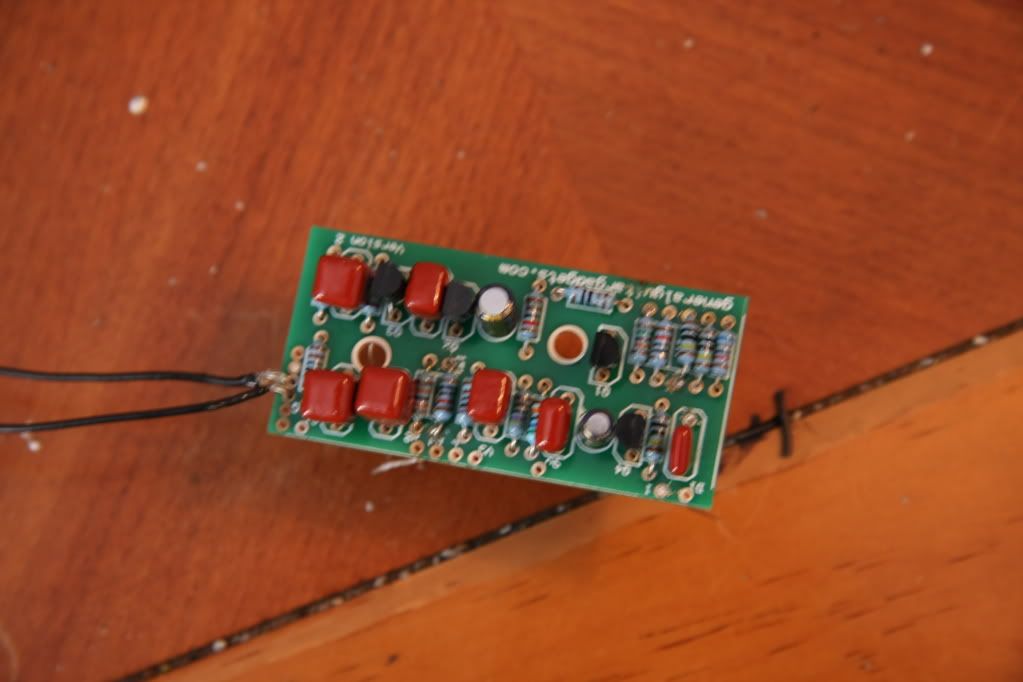
    *First thing, check the board for broken etches etc.
    *Then for each component you install, double-check you have the correct value/part/orientation. Unsoldering stuff becomes a messy affair.
    *I usually start with resistors, then caps, and transistors/opamps last.
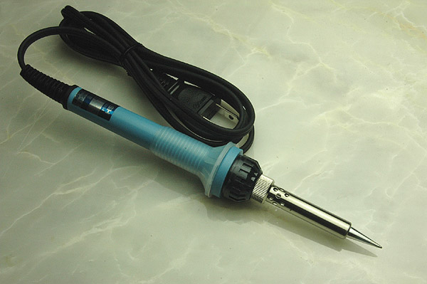
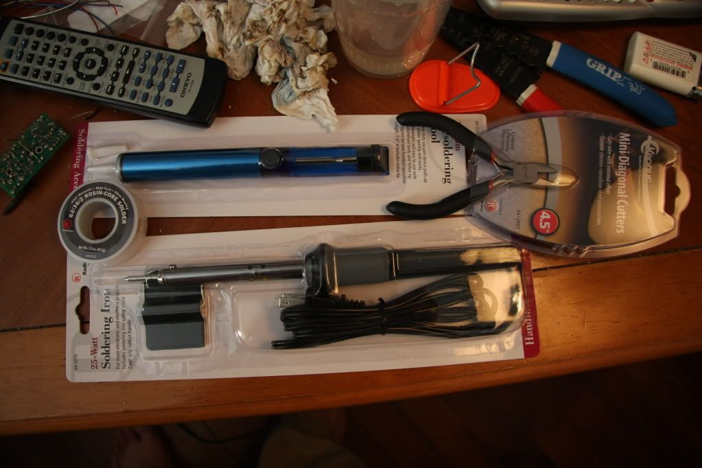
    *Don't know what soldering iron you're using, but I have a 40w which is OK, but I think it gets a little too hot sometimes.
    *The tip needs to be fine if you want a clean job. And keep the tip clean, I usually clean it after a couple of runs.
    *For Opamps, use IC sockets (which should be provided in the kit, but not 100% sure). That way you won't cook the chip and it'll save you a lot of hassle if you accidently insert it upside down/backwards.
    *Some people usually do the same for the transistors, which is probably a good idea.
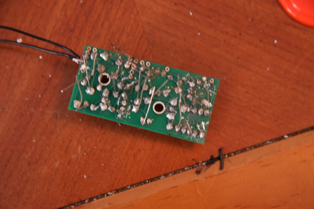
    *After everything is installed and you've checked the work again for bad joints, incorrect placement of components etc, it's probably a good idea to give the solder-side of the board a clean. I use a toothbrush (an old one, not my wife's) and nail polish remover (my wife's).
    *For wiring to jacks/pots etc, I like to make the wires a little long, then cut them to size after routing. I usually like to run the wires so they run around the inside edge of the box. It looks a lot tidier (IMHO).
    *Also, just remember, when you're installing the board into the box you're going in from the bottom, so the jacks will be reversed (i.e the i/p jack is now on the left, and the o/p on the right).
    *The jack with 3 connectors is the i/p jack and the one with 2 connectors is for the o/p.

    I've probably told you stuff you already know, but anyway, good luck and happy building. It gets quite addictive (and if you're like me, probably end up building boxes you don't really need).

    P.S: Here's a resistor colour code chart so you can verify the values before insertion.
    Guitars: Epiphone SG-400 Custom; Epiphone Firebird V; 1996 Gibson LP Standard; Avion 4; Yamaha FG-301B acoustic

    FX: TS-808; Big Muff (Triangle Version); Red Llama; Green Ringer Octave Up (Clones); Maxon Phaser; Maxon Compressor; Tremulus Lune Tremolo; Line 6 POD II

    Amp: (Somewhere in another country) Hiwatt 100W head, Marshall 4x12 cab

    My noise here

  3. #3
    Join Date
    Sep 2007
    Location
    Clarksburg, WV
    Posts
    209
    Post Thanks / Like

    Default

    Thanks for the tips. I did my best to do what you said and I've definitely learned some things already. First off, desoldering is really annoying and messy (as is attempting to get through a hole that has accidentally had solder melted into it). I have also learned that you will be most successful by using just enough solder and getting a good seal on the first melt. It seems like the more times i try on some parts it just doesn't want to hold and the more solder I use the messier it gets with no correlation to the piece staying put. One of the major roadblocks I have run into is that the iron I am using is just not small enough and I have reached the point at which i need to run the small group of wires where all of the holes are basically touching b/c they are so close. I don't have the slightest clue how to make this work. With the iron I have been using there is no way I will be able to get these wires connected without making one massive connection with a 4 wires. Any ideas or tricks for this problem? Is it really just about me getting a better iron? Thanks again for the help.

  4. #4
    Join Date
    Aug 2008
    Posts
    323
    Post Thanks / Like

    Default

    Before you go any further, how big is your iron? The size you should be using is like this:

    25W


    If you're trying to use something much larger than this, you'll get yourself into trouble. Yeah, each solder point should be a "1-shot" i.e you shouldn't try to solder multiple times in the same place. The joints become "dry" (if you look closely, instead of a nice shiny joint (good), it looks cloudy and "bubbly" (bad)). If you show me what you've done so far by way of photograph, maybe I can offer some advice on how to fix it. My job in a previous life was repairing PC and monitor boards, so I have some experience in this area. You can PM me if you like.
    Guitars: Epiphone SG-400 Custom; Epiphone Firebird V; 1996 Gibson LP Standard; Avion 4; Yamaha FG-301B acoustic

    FX: TS-808; Big Muff (Triangle Version); Red Llama; Green Ringer Octave Up (Clones); Maxon Phaser; Maxon Compressor; Tremulus Lune Tremolo; Line 6 POD II

    Amp: (Somewhere in another country) Hiwatt 100W head, Marshall 4x12 cab

    My noise here

  5. #5
    Join Date
    Feb 2006
    Location
    Uppah Noo Yawk
    Posts
    7,407
    Post Thanks / Like

    Default

    Excellent tips from Suhnton, quite comprehensive. Just a couple of things to add:

    • A 40W iron for this kind of work is w-a-a-a-y-y too big. I'd recommend an iron in the 20 - 25W range. I'm on my 3rd one of THESE, and they work very well for this service. BTW, I'd recommend the 0.032" diam. 60/40 tin-lead rosin-core solder from Radio Shack. Stay away from the non-leaded type, unless you you have a masochistic streak. Believe me, the planet isn't going to implode because we DIY pedal-makers use the leaded stuff....
    • For DIY beginners: Read the kit instructions thoroughly before you start. Then read them through a second time before picking up your soldering iron. Now put the iron down and read 'em a third time. No kidding. The more familiar you are with this, the less likely you are to make beginner mistakes. As you mentioned, desoldering tends to be a rather large PITA. This will help avoid it.
    • Which brings me to key supplies to perform desoldering effectively, when you have to. Desoldering braid is an absolute essential--get some. A desoldering bulb is helpful for cleaning out plugged eyelets. And if you think you'll be doing more of this, a proper desoldering tool is better yet.
    Hope that helps. Take your time and ask questions if you get stuck....
    DVM's Ever-Expanding Gear List:

    Guitars - W-A-A-A-Y-Y too many to list. Check 'em all out HERE

    Amps & Cabs - "Kap'n Kerrang-aroo" BYOC 18W TMB kit amp head; Mojave Coyote head; Fender Hot Rod Deluxe Lacquered Tweed Ltd. Ed.; Allen Sweet Spot kit amp; BYOC Tweed Royal kit amp; Epiphone Valve Jr. combo + mods; Drive 2x12 cab / Celestion G12M Greenback + G12H30; AB Custom Audio 1x12 cab / Celestion Alnico Blue

    Pedals/Effects - ZILLIONS, including DVM's Home-built Pedals - See some HERE and HERE, TOO!

    DVM's Gear Photos
    Visit MY WEBSITE!


  6. #6
    Join Date
    Sep 2007
    Location
    Clarksburg, WV
    Posts
    209
    Post Thanks / Like

    Default

    Well I made a trip to radio shack today. I have learned first hand the importance of having the right tools. Now that I understand this I really laugh at how gross this project looks at this point. Here's a few pics for laughs.


    This side looks ok.


    This side looks like solder was barfed all over the circuit board.


    Got this fun stuff from radioshack. Right now the plan is to just take it all apart, clean the board as best I can and then start over. I haven't even cut a good few of the wires because my wire cutters were a joke. Now I have some good ones so that shouldn't be a problem.

    Quick question about order of application. Do you guys thing it's easier to start with the smallest items (Resistors) and then go to the larger items, or do you prefer to move in one direction across the board so that you always have a clean angle to the point that you are soldering? It seems like the second method might be a little easier, but I don't know. Also, are there any special tricks to restoring the solder points so they are not dry and will take the new solder well? Thanks again. I cannot stress enough how much better I feel about doing this stuff while knowing that I can ask you guys for answers.

  7. #7
    Join Date
    Jan 2008
    Location
    bend,or.
    Posts
    2,311
    Post Thanks / Like

    Default

    Well you are getting practice in.I wouldn't desolder it,try and clean it up and see if it works.Take it apart and it will become a real mess.Sumi
    Guitars,Warmoth Tele,90's Fender Strat Plus/Fender CV 50's Tele/Parker p-36/Fretlight/Custom Strat(Fender body/warmoth Clapton neck,tonerider pups)Larrivee L03 mahogany acoustic

    Amphs/66 Super Reverb/60's Bandmaster head and 2/12 cab/Blues jr//epi valve jr/supro super/ ZT lunchbox/Mahaffay Little Laneilei 3350/Pignose g40v

    Pedals/Voods Rodent/MXR carbon copy/Duncan Pickup booster/Ts9/Rat/ts10/Line 6 tone port uk2
    Line 6 M13

  8. #8
    Join Date
    Aug 2008
    Posts
    323
    Post Thanks / Like

    Default

    If you cut the legs off the components and clean the underside off with alcohol, it might not look as bad as you suspect. I've seen repair jobs worse than that.

    You could try desoldering some of the messier joints.
    You don't have to get every last bit of solder out, just aim for removing the excess.
    Then give the joint a quick solder shot. It should be a "touch-and-go" type action. It might take a little practice, but you'll get the hang of it quickly.
    Don't hold the soldering iron on the component and "feed" the solder in.
    Don't try to remove the components or you'll break an etch.

    Also to answer your question, when soldering components in, the board should be sitting on the table/bench (don't try to solder with one hand while holding the board in the other). Therefore put components that sit relatively flat to the board in first i.e resistors, then gradually build up so that the components that sit proudest (stick up the most) go in last. It's a lot easier that way. That's how I do it anyway. Wiring always goes in last for me.

    Good luck.
    Guitars: Epiphone SG-400 Custom; Epiphone Firebird V; 1996 Gibson LP Standard; Avion 4; Yamaha FG-301B acoustic

    FX: TS-808; Big Muff (Triangle Version); Red Llama; Green Ringer Octave Up (Clones); Maxon Phaser; Maxon Compressor; Tremulus Lune Tremolo; Line 6 POD II

    Amp: (Somewhere in another country) Hiwatt 100W head, Marshall 4x12 cab

    My noise here

  9. #9
    Join Date
    Sep 2007
    Location
    Clarksburg, WV
    Posts
    209
    Post Thanks / Like

    Default

    Ok...I've cleaned it up quite a bit. Everything looks really good but i just can't get this one last leg to stick. I have cleaned it the best i know how. Cleaned the iron and then done the cleanest solder job I can. It just wont stick to the eyelet. Is there anything else I can try that I haven't tried yet? I really really don't want to have to scrap the job because of this one stupid solder joint. It's driving me crazy haha. Pleaseeee tell me theres something simple I can do!

  10. #10
    Join Date
    Aug 2008
    Posts
    323
    Post Thanks / Like

    Default

    If it's not sticking to the eyelet it probably means the etch has come away/off. Can you take a photo? If that's the case, there are a couple of options:

    1)
    At the end of the track that the eyelet connects to, scrape away the coating to reveal the bare copper track.
    Be very careful if/when you do this, and always scrape in the direction of the eyelet. This will prevent the track from lifting off the PCB.
    You should scrape only enough away to allow soldering to the track (3 or 4mm). Then, either:

    A) Fold the leg over, cut it to size and solder directly to the track or
    B) Using fine wire, do a couple of wraps around the leg, solder and then cut and solder the wire to the track.

    2)
    The other option is to run a wire connection from the component leg to the other end (where it should connect to). For beginners, this might be easier/safer than scraping away the coating.

    If you can post up a photo, it will be easier to assess what needs to be done.

    Cheers.
    Guitars: Epiphone SG-400 Custom; Epiphone Firebird V; 1996 Gibson LP Standard; Avion 4; Yamaha FG-301B acoustic

    FX: TS-808; Big Muff (Triangle Version); Red Llama; Green Ringer Octave Up (Clones); Maxon Phaser; Maxon Compressor; Tremulus Lune Tremolo; Line 6 POD II

    Amp: (Somewhere in another country) Hiwatt 100W head, Marshall 4x12 cab

    My noise here

  11. #11
    Join Date
    Sep 2007
    Location
    Clarksburg, WV
    Posts
    209
    Post Thanks / Like

    Default

    I think it may be the case that the etch has come off over the eyelet. I had thought about bending the lead over and soldering it down, but I have no clue about those sort of things. I'll take a picture and get it up tomorrow before I do anything else to that particular part.

  12. #12
    Join Date
    Aug 2008
    Posts
    323
    Post Thanks / Like

    Default

    Yeah I was thinking about it after I posted my response earlier.
    I would definitely recommend option 2 (running a new wire connection from the "broken etch component" to the other end). I think overall the job will look tidier.
    Guitars: Epiphone SG-400 Custom; Epiphone Firebird V; 1996 Gibson LP Standard; Avion 4; Yamaha FG-301B acoustic

    FX: TS-808; Big Muff (Triangle Version); Red Llama; Green Ringer Octave Up (Clones); Maxon Phaser; Maxon Compressor; Tremulus Lune Tremolo; Line 6 POD II

    Amp: (Somewhere in another country) Hiwatt 100W head, Marshall 4x12 cab

    My noise here

  13. #13
    Join Date
    Feb 2006
    Location
    Uppah Noo Yawk
    Posts
    7,407
    Post Thanks / Like

    Default

    Is your problem that the top part of the eyelet etch has come off, but you still have continuity between the rest of the eyelet (hopefully the eyelet on the component-side of the board is still there) and the trace it attaches to? If so, a simple trick may be just soldering the lead on the component side of the eyelet, as long as it's accessible. I've done this a couple of times with good results. Just check for continuity between the eyelet (either side of the board) and the terminus of the trace it connects to.

    If, on the other hand, the eyelet has detached from its trace, that method won't work. A good trick for that situation is similar to Suhnton's second suggestion, but using the component lead itself as a "quasi-trace". Locate where the connecting trace for the eyelet goes to, then bend the component lead over and spot solder it to that point. In practice, this usually works only for short traces, and you have to be sure that the bare metal lead isn't going to short against anything else in between. If that's a problem, use a length of insulated hook-up wire instead, per Suhnton's option 2. I agree with him that you're better off avoiding trying to scrape on the trace. That's pretty easy to screw up.

    And don't sweat it--problems of this sort are virtually always fixable. Might not look too great, but once you button up a pedal, as long as it works reliably, nobody cares what it looks like inside....
    DVM's Ever-Expanding Gear List:

    Guitars - W-A-A-A-Y-Y too many to list. Check 'em all out HERE

    Amps & Cabs - "Kap'n Kerrang-aroo" BYOC 18W TMB kit amp head; Mojave Coyote head; Fender Hot Rod Deluxe Lacquered Tweed Ltd. Ed.; Allen Sweet Spot kit amp; BYOC Tweed Royal kit amp; Epiphone Valve Jr. combo + mods; Drive 2x12 cab / Celestion G12M Greenback + G12H30; AB Custom Audio 1x12 cab / Celestion Alnico Blue

    Pedals/Effects - ZILLIONS, including DVM's Home-built Pedals - See some HERE and HERE, TOO!

    DVM's Gear Photos
    Visit MY WEBSITE!


  14. #14
    Join Date
    Aug 2008
    Posts
    323
    Post Thanks / Like

    Default

    Quote Originally Posted by duhvoodooman
    nobody cares what it looks like inside....
    That's right, look at them Jetters - hot melt glue everywhere
    Guitars: Epiphone SG-400 Custom; Epiphone Firebird V; 1996 Gibson LP Standard; Avion 4; Yamaha FG-301B acoustic

    FX: TS-808; Big Muff (Triangle Version); Red Llama; Green Ringer Octave Up (Clones); Maxon Phaser; Maxon Compressor; Tremulus Lune Tremolo; Line 6 POD II

    Amp: (Somewhere in another country) Hiwatt 100W head, Marshall 4x12 cab

    My noise here

  15. #15
    Join Date
    Sep 2007
    Location
    Clarksburg, WV
    Posts
    209
    Post Thanks / Like

    Default

    Ok cool. I'll try DVM's suggestion of soldering on the other side of the board I think. Yet again, something I never would have thought of haha. Hopefully this will be the last of my troubles with this build.

  16. #16
    Join Date
    Sep 2007
    Location
    Clarksburg, WV
    Posts
    209
    Post Thanks / Like

    Default

    well...i got that one spot fixed i believe. It's all wired together and whatnot. I get a signal when the pedal is engaged but it doesn't trem. It also sounds a little bit distorted. The signal light and the pots also aren't functional haha. Sounds like I have some step by step trouble shooting to do.

  17. #17
    Join Date
    Aug 2008
    Posts
    323
    Post Thanks / Like

    Default

    The first place you want to check is that trouble eyelet spot. Are you sure there's continuity between the components?
    Guitars: Epiphone SG-400 Custom; Epiphone Firebird V; 1996 Gibson LP Standard; Avion 4; Yamaha FG-301B acoustic

    FX: TS-808; Big Muff (Triangle Version); Red Llama; Green Ringer Octave Up (Clones); Maxon Phaser; Maxon Compressor; Tremulus Lune Tremolo; Line 6 POD II

    Amp: (Somewhere in another country) Hiwatt 100W head, Marshall 4x12 cab

    My noise here

  18. #18
    Join Date
    Feb 2006
    Location
    Uppah Noo Yawk
    Posts
    7,407
    Post Thanks / Like

    Default

    I'd be double checking all your wiring connections. The fact that the LED doesn't light suggests that something isn't connected properly somewhere. Confirm that you didn't install the LED backwards--they only light up in one direction.

    Am I right to assume that in bypass mode, everything is working correctly?

    Clearly focused, close-up photos are really needed to effectively troubleshoot....
    DVM's Ever-Expanding Gear List:

    Guitars - W-A-A-A-Y-Y too many to list. Check 'em all out HERE

    Amps & Cabs - "Kap'n Kerrang-aroo" BYOC 18W TMB kit amp head; Mojave Coyote head; Fender Hot Rod Deluxe Lacquered Tweed Ltd. Ed.; Allen Sweet Spot kit amp; BYOC Tweed Royal kit amp; Epiphone Valve Jr. combo + mods; Drive 2x12 cab / Celestion G12M Greenback + G12H30; AB Custom Audio 1x12 cab / Celestion Alnico Blue

    Pedals/Effects - ZILLIONS, including DVM's Home-built Pedals - See some HERE and HERE, TOO!

    DVM's Gear Photos
    Visit MY WEBSITE!


  19. #19
    Join Date
    Sep 2007
    Location
    Clarksburg, WV
    Posts
    209
    Post Thanks / Like

    Default

    The bypass mode worked well. It was when I clicked the pedal on that it got kind of distorted sounding. I will try switching the led light and see if that helps. I'll also try and get some pictures tonight to see if you guys can find anything blatantly obvious.

Page 1 of 2 12 LastLast

Posting Permissions

  • You may not post new threads
  • You may not post replies
  • You may not post attachments
  • You may not edit your posts
  •