Warning: preg_replace(): The /e modifier is deprecated, use preg_replace_callback instead in ..../includes/class_bbcode.php on line 2958

Warning: preg_replace(): The /e modifier is deprecated, use preg_replace_callback instead in ..../includes/class_bbcode.php on line 2958
Crate V5 mods... anyone? - Page 11
Page 11 of 25 FirstFirst ... 91011121321 ... LastLast
Results 191 to 209 of 465

Thread: Crate V5 mods... anyone?

  1. #191
    Join Date
    Jan 2009
    Posts
    357
    Post Thanks / Like

    Default Adding reverb to The V5 or other EL84 amps

    Quote Originally Posted by SciHi
    I would be interested in more details on your reverb mod/addition to the v5. Like a schematic, if possible. Thanks for sharing the technical detail for those of us still learning...
    Adding reverb to the V5 or Valve Jr. is not that hard to do relative to your skill level at bread boarding circuits. Not sure if any one has offered this modification in a kit level but a good chance if someone did it could be made to work in most of the EL84 amplifiers on the market now. With the Valve Jr. amplifiers I have they used the same transformer as the Epiphone Valve Special that had +/- 18 volt AC secondary they used for +/- 15 volt DC supplys for a DSP. Not sure why someone had the bright idea to run your main signal path through a DSP (analog to digital to analog?), looks like they don’t make the Special anymore I wonder why? I will probably do this mod in multiple posts, sure I will forget something and need to have a lot of attachments to illustrate the mod. The reverb tank that I think is the best choice is an Accutronics 8BB2A1B this is 190 ohm input, 2275 ohm output medium delay, input and output grounded, no lock and open side down. You can find the secret decoder table for reverb model numbers at Accutronics web site. They also have schematics for drive and recovery circuits that differ from the ones that I use. One problem with the 8BB2A1B is that the input is grounded, for the drive circuit I am using it needs to be isolated. So you will need to carefully drill out the rivets that hold the input RCA connector and remount the input connector PCB with nylon or rubber washers and screws with nuts to isolate it. No one has this tank in stock with an isolated input that I know of. As reverb tanks go the lower the input impedance the greater the operating frequency range, so using an 8 ohm tank would be great but that requires around a 1 watt audio amplifier to drive the reverb tank. Plus 190 ohm input should be good to approx 3 kHz which is about as far as the guitar is going to go anyway. The best price I have found for this tank is 22.95 at Antique Electronic Supply (www.tubesandmore.com) they have some neat t-shirts too, ok prices on tubes and capacitors. May as well look around and get what you may need to help offset the shipping and handling charge while you are there. Oh they did have some RCA cables real cheap in clearance and you will need one for this.
    For the reverb driver circuit I suggest using the Texas Instruments TLE2072 or TLE2071 this is a fet input op amp with low output impedance and good output current capability it cost around 2.50 but splurge your worth it. I would not use the NE5532 because it has low input impedance and will load down the volume pot and change the input bandwidth, while the TL074 (a FET input) has low output current capability. About the drive circuit, in the schematic C1 is going to connect to the wiper of the volume pot you will need to add a 220k resistor in series with volume pot wiper to grid of second triode(will post marked up schematic in future). C1 and R1 are a high pass filter with 3db down at approx 330Hz, low frequency signals in the reverb tank will make it sound muddy so this blocks them. If you are all about control and want to have a dwell control (input level control) on the input to the reverb tank then use a 1 Meg log pot for R1 and connect its wiper to + input of op amp. R3 sets the current through the reverb tank you can play around with this value by plus and minus 50 ohms. Because the reverb input is the same as an inductor its input impedance will double per octave, 190 ohms at 1 kHz to 380 ohms at 2 kHz… ECT. R6 will limit the maximum impedance in the op amp feed back path so the op amp will not get pasted into a supply rail.
    I have attached pictures of the Accutronics and Ruby reverb tanks the case of the Ruby is nicer looking then the Accutronics and has nylon vibration isolation bushings standard. The Ruby tank also has small PCB inputs that have jumpers to make or break the isolation of the inputs and outputs. While I like the guts of the Accutronics better its more old school with the brass and solder connecting the magnets attached to the springs. The Ruby is the stock OEM tank from a Crate V50 that I will upgrade to a long tank.
    That is it for now if you are ordering parts you may want to wait to see the reverb recovery circuit first that I will post soon. By the way if you kept the stock op amp in one piece you will be able to use it for the recovery amplifier. Also if you can figure things out for yourself as far as op amps you could buffer an NE5532 with one of the TL072 op amps so you can use that as a reverb driver then use the other half of the TL072 as the recovery amplifier.
    All for now more to follow.

    PS: If you are adding reverb check post #364 there I changed the reverb recovery circuit to a differential amplifier and used a jfet buffer in the tank on the reverb output. If you stay with the reverb recovery circuit in these posts you should isolate both the input and output RCA jacks and run a separate ground wire to the reverb tank chassis for lower noise. Also can’t hurt to put metal tape or a metal plate under the reverb tank to help reduce noise the plate or tape needs to be grounded also.
    Last edited by jim p; December 31st, 2009 at 09:48 AM.

  2. #192
    Join Date
    Jan 2009
    Posts
    357
    Post Thanks / Like

    Default Adding reverb part 2

    Previously on Modding the V5. In the previous post I covered the reverb tank driver circuit, now for the recovery amplifier. Here is where you get to use that TL072 op amp if you still have it in one piece. Looking at the attached schematic of the reverb recovery circuit I have made a change from most recovery circuits by adding C2 as a high pass filter. Because on the V5 that I have added reverb to, before adding reverb I had no 60 Hz hum at all (That 1 Hennery choke in the plate supply does wonders) now I have some with high levels of reverb (space the final frontier levels). As noted on the schematic a value of 100nF maybe better at blocking the 60 Hz hum. Moving on to the feed back loop of the op amp C1, R2, R3 and C3 the value of C1 keeps the op amp at unity gain at DC with a 3db down point at 140Hz this maybe another capacitor you could lower to reduce hum by changing to 220nf. If you know op amps you can see that you have plenty of gain (R3/R2 +1) approx 43 times the signal from the reverb tank. Across the feed back resistor R3 is C3 this will roll off the maximum output frequency of the amplifier at approx 4 kHz which will help prevent the possibility of oscillation of the op amp (also limit of reverb tank bandwidth). The output of the amplifier is coupled to the output level control through C4 by my calculation you maybe able to use a value of 220nf instead if you wish. Also if you added a resistor in series with the pot you could set a limit on maximum reverb level if you want. The wiper of the reverb level pot is going to be connected to R7 (220k ohms) on the Crate V5 PCB. The grounded side of R7 needs to be removed from the PCB and connected to the pot so R7 will be connected to the grid of the tube on one side and the reverb pot on the other. In the previous post I stated you need to add a 220k resistor from the wiper of the volume pot to the grid of the tube, this will sum the clean signal and the reverb signal at the grid of the tube. You will also need to add a 100 to 330pf cap from the grid of the tube to ground to help reduce or prevent reverb feedback. This mod keeps the clean signal path pure tube so you are stuck with the possibility of reverb feedback at high reverb level settings. If an op amp was used to buffer the output of the volume pot it would prevent this (you could use a cathode follower tube ckt also but). Or if an op amp was used as a summing amplifier for the clean and reverb signal this would also prevent the possibility of feedback. But the feedback will let you know the reverb is working so just consider it a test signal or you can use it to get peoples attention. One detail that is not on the schematics is decoupling of the power supplies on the bread boards I have 22-50 ohms in series with the +/- supplies with 22uf tant to ground. I took the supplies from C12+ and C13- to get approx 18 volts. If you have removed IC1 the op amp in the PCB you could reduce R19 and R20 to get +/- 18 volts at C10+ and C11- (you will need to have this circuit wired in and working to determine the value needed). I wanted greater then +/- 15 volts for maximum headroom for the op amps by there spec you could go as high as +/- 19 volts. Also I did not decouple the driver amplifier and recovery amplifier separately if you want to go for it. I would put decoupling on your proto board though because it will be located a distance from the power supply.
    Next stuff to cover is hard wiring the RCA cables or installing female RCA Oh! Not politically correct sorry my bad, I meant RCA receptacles on the chassis. How to mount the reverb tank in the cabinet. How you mount the proto board is up to you.
    Anyway see attachments.
    Also in previous post you can see 9 volt battery clips on the proto board, I used two half dead 9 volt batterys to test the op amps before installing the board. I have a scope and signal generator to work with if you only have a meter I have to think of what you could do to test the board first.Maybe we can use the guitar as a signal generator and look for AC volts at the output of the op amp on both circuits. After an initial DC test of the circuit.
    Any mistakes here please let me know,thanks.
    Last edited by jim p; April 11th, 2009 at 07:45 AM.

  3. #193
    Join Date
    Jan 2009
    Posts
    357
    Post Thanks / Like

    Default testing the reverb drive and recovery proto board

    Now that you built the reverb drive and recovery circuit how do you test it? What I have done is to attach two 9 volt battery clips for the +/- 18 volt supplies for DC and signal tests. So attach the clips and plug in the batteries hope you have decoupling resistors in series you can use them to check the supply current. On the board I built with one TL072 and one TLE2071 the positive and negative supply current was approx 8mA on each supply. So you can measure the voltage drop across the decoupling resistor divide it by the resistor value to calculate the supply current. If you have from 6 to 18mA per supply you are doing good so far. Next measure the voltage at the output pin of both amplifiers (pin 6 on single op amp, pin 1 or 7 on a dual) there voltage should be approx 0 volts with no signal.
    Now for the signal test. Disconnect both batteries. What I did was to attach a ¼” jack to use a guitar as the input signal. You attach the jack at the same point where you will connect the volume pot to the reverb driver amplifier. Next connect the reverb driver amplifier output to the input of the reverb recovery amplifier. You will now need a cheep little high impedance speaker, old earphone, transistor radio speaker, alarm clock radio speaker whatever you have or can find. With a large value non polar capacitor 10uf or greater (you can make a non polar capacitor by connecting two polar capacitors plus to plus or minus to minus that will be equal to half there value) in series connect the speaker to the output of the reverb driver amplifier. Plug the guitar into the input connect the two batteries strum the guitar and listen. It might sound crummy but if you hear it you are good so far. Next unplug the batteries and move speaker connection to output of recovery amplifier. Reconnect the batteries and play away, sound coming out good you are all set to stick this puppy in the amplifier. If any of these tests fail look around for bad connections get your ohmmeter out and start seeing where things went wrong.

    Regarding the supply rails to the amplifier circuit having less then 18 volts is probably OK. I have been calculating the maximum peak voltage required to drive the reverb tank and that looks to be approx 10 volts peak at 4 kHz so +/- 15 volts should be fine.
    See the attached picture and schematic

  4. #194
    Join Date
    Jan 2009
    Posts
    357
    Post Thanks / Like

    Default mod reverb tank input and chassis mounting

    On to the reverb tank. As I said in the previous post you will need to isolate the input to the reverb tank. I have done this by using a drill bit and routing out the rivets by hand not using a power tool. I also used a pair of diagonals to cut away the rivets. The reverb tank is not meant to take a lot of abuse so I think a power tool would be risky. In my case I have removed the spring assembly first because I am swapping the guts of the Accutronics with the Ruby tank. I am going to make a head amp out of the third Crate V5 so the reverb tank will be visible and the Ruby looks nice on the outside. After you get the input RCA connector free from the reverb chassis you will need to put insulation between it and the chassis then reattach it with screws and nuts. I used nylon washers for insulation and nylocks for the nuts. Nylocks are the nuts with a cinched in unthreaded nylon washer attached so they will not fall off due to vibration or failure to tighten completely. These are great to use on an amplifier so you do not need to worry about a loose nut floating around shorting out the amplifier. If you do not use nylocks I would use some loctite, nail polish or paint on the nuts to prevent them from coming loose.

    Mounting the reverb tank in the amplifier. To do this I used 8-32 x 1 ½” hanger bolts, mounting the tank on the bottom of the amplifier cabinet. Hanger bolts are wood screws on one end and machine threads on the other. You will probably need to remove the speaker and possibly the baffle board to get easy access to mount the tank. Also will need to remove the lower back panel and using a flat blade screwdriver and pliers remove Velcro straps on bottom of cabinet (remove speaker first to avoid damage). To locate the placement of the four holes set the reverb tank on the inside bottom of the amplifier, place it in a location that will clear the speaker and allow for the connection of the RCA cables. Then mark the center of the four holes on the outside corners of the reverb tank. Next drill a small pilot hole be careful to not drill through to outside of the cabinet if in doubt put a piece of masking tape on the drill bit as a guide for the hole depth. You will need two nuts on each screw to lock them against each other for both installation of the screws into the cabinet and to hold the reverb tank. Screw the hanger bolts into the bottom of the cabinet again be careful to not go so far as to break through to the outside of the cabinet. Now you will need washers, nuts and springs, rubber or foam to mount the tank so it is isolated from the cabinet. This is to reduce pickup of the sound from the speaker which will muddy the sound produced by the reverb tank. In the attached picture you can see that I used springs for this. Use two nuts on each screw to lock them together but allow for free movement of the reverb tank.
    Note one thing that may work to suspend the reverb tank is to cut up and use the foam that is packed into the reverb tank to protect it for shipping. Also you could use a bag to mount the tank but unless it is padded I don’t think it will isolate the tank from vibration.
    PS If you have a fear of routing out the rivets on the tank I suggested as a second choice the 8DB2C1B tank. This is a 310 ohm input, isolated input tank the input current requirement is approx the same but you will loose bandwidth vs the 8BB2A1B
    Last edited by jim p; April 14th, 2009 at 04:58 PM.

  5. #195
    Join Date
    Feb 2009
    Posts
    35
    Post Thanks / Like

    Default

    Quote Originally Posted by jim p
    Adding reverb to the V5 or Valve Jr. is not that hard to do...
    Thanks Jim, I have a selection of opamps and project board to build one. I will let you know how it turns out.

    SciHi

  6. #196
    Join Date
    Jan 2009
    Posts
    357
    Post Thanks / Like

    Default mounting of reverb level control and proto board

    Last thing is where to put the proto board and the reverb level control. I have installed the proto board on the input jack side of the main PCB. I used the two screws that hold the PCB to connect brackets that I have standoffs attached to that hold the reverb amplifiers. Another way to go would be long metric screws with pass-through standoffs (a cut up Bic pen cylinder) to hold the reverb amp board. I have mounted the reverb level pot on the back of the chassis next to the speaker jack. I did not want to mess with front panel. But if you move the power indicator to above the power switch. The spacing is about right for putting the level control where the power indicator was. (See picture) So if you get a pot and knob from Crate it will look almost stock. Crate has a 20k audio pot in there tone stacks on V18, V33 and V50 or change to different knobs that match.
    Guess I am leaving out mounting of RCA cable to PCB. I just hardwired to the board and ran the cable out a ventilation slot on the chassis. Mounting a dual RCA receptacle would be the best but I am not that crafty.

  7. #197
    Join Date
    Apr 2009
    Posts
    1
    Post Thanks / Like

    Default sucess

    Thanks for the directions Jim. I managed to make your first mods without screwing the thing up.

    Gary

  8. #198
    Join Date
    Feb 2009
    Location
    Wichita, Kansas
    Posts
    17
    Post Thanks / Like

    Cool Thanks Jim P

    Thanks Jim, I'm still messing around and messing things up. I get it going good then I try to improve it and then back to the drawing- uh I mean circuit board. I'll try to keep this short as possible as I read it is a guitar player (which I am) thread and not a PCB modification thread but we electric players do need amps so the neighbors can hear us. I think the major problem with this amp- other than the obvious- is the power supply puts about 330 volts on my EL84 plate. The tube is designed to handle 300 volts max. I found a way to rectify this but my screen grid was then way more than my plate voltage. So then I went to lowering my screen grid and on and on....Going to the hospital so I'll have a couple weeks of recovery to again rectify the current problem. We have one electronics store in this one horse town other than radio shack so I have problems getting resistors that fit those tiny holes with the correct ratings. What I really want is more good clean headroom. Is that more than I can ask from a 5 watt single ended amp? Wish it had a tube rectifier See you guys in a couple weeks.

  9. #199
    Join Date
    Jan 2009
    Posts
    357
    Post Thanks / Like

    Default reply to flyk35r

    Quote Originally Posted by flyk35r
    Thanks for the directions Jim. I managed to make your first mods without screwing the thing up.

    Gary
    thanks for the feedback glad things are working for you.

  10. #200
    Join Date
    Jan 2009
    Posts
    357
    Post Thanks / Like

    Default high plate voltage

    I don't think the plate voltage being on the high side is a problem as long as the plate current is low enough to keep the plate at 12 watts. When the output tube goes positive there is better then 400 volts on the plate from transformer flyback. If you want to see a tube out of speck go to the Fender site and open the schematic for the Champ 600 they have 14 watts on a 12 watt tube and screen grid at 360 volts, should be 285 volts or less.

  11. #201
    Join Date
    Jan 2009
    Posts
    357
    Post Thanks / Like

    Default Adding a presence control (feedback) to the V5

    Another modification you can add to the V5 is a presence control which is adjustable negative feedback. Not sure why I have to state negative feedback because positive feedback would turn the amplifier into an oscillator. What I have done is to remove C8 the cathode bypass capacitor on the second triode and put a 10k pot with 22uf in series in parallel with R8. Then I found I needed to reverse the wires to the ¼ inch output jack to the speaker so orange to ground and black to the tip of the ¼ inch jack. You should also check that the J4 connection is a brown wire while J5 should be a red wire. Then from the black wire to the speaker jack I connected a 57k ¼ watt resistor to the cathode of the second triode. I wired the pot as a rheostat so maximum resistance is full clockwise equal to full feedback. Then if you dial the pot full counter clockwise the 22uf is in parallel with R8 and as the amp is stock you have no feedback.
    What feedback will do is when the output tube is shutting down its control grid is going negative then its plate supply, the transformer inductance and speaker inductance is taking the output tube plate positive (flyback). If it goes more positive then it should relative to the input at the grid of the second triode the triode will shut off turning the output tube on pulling the plate voltage down. So with feedback there will be less distortion in the output signal. Almost all Fender amplifiers the Champ included have negative feedback. With feedback you will notice a loss in gain relative to the volume pot setting without feedback. Also the amplifier may not sound as bright, the brightness due to harmonic distortion that will be reduced by feedback.
    A quick way to try out feedback without mounting the pot someplace would be to just remove C8 and install the 57k feedback resistor from the transformer secondary to the cathode of the second triode and see how you like it.
    On the positive feedback front I never did it to see how bad that would be because if you do it wrong that is what you will have. What should happen is a constant screech or motor boating sound coming from the amplifier. If you do the whole mod with a pot you can set to the no feedback position then slowly dial in feedback if everything is right no odd noises.
    See attached schematic and pictures.
    Let me know of any errors, thanks

    I am going to post scope pictures of what the output signal looks like with and without feedback. Also with resistor load vs. speaker as a load.

  12. #202
    Join Date
    Jan 2009
    Posts
    357
    Post Thanks / Like

    Default Using a resistor to simulate a rectifier tube

    Instead of having a rectifier tube for plate voltage sag you can just use a watt wasting resistor in the plate supply. For someone that wants that old time amplifier supply voltage sag they would get because the amplifier had a rectifier tube the cheep and switchable solution is to use a 500 ohm 3 watt to 1k ohm 5 watt in series with the plate supply voltage on the V5 with a low value cap after it say 10uf 450 volts on the output side of the choke. If you add a switch across this resistor you now have both sag and new world diode rectifier no sag settings. This is a feature that Mesa Boogie has on some of there amplifiers go to the Schematic Heaven web site and check through the schematics there to see.

    Another way to go would be to put the resistor on the input side of the choke so between the rectifier bridge and the first filter cap C14 and bleeder resistor R24. Now that I think about it this would be a better simulation on having a tube rectifier. There use a 54 ohm 5 watt to a 120 ohm 5 watt resistor. When you look at tube rectifier data sheets they need to have a choke on there output in some cases because the high instantaneous current of having a capacitor on there output would have fried them. Another plus factor of tube rectifiers was there lag on power up allows the filament supplies to heat up the tubes before the plate supply comes up, so this was like a built in standby switch on power up with less stress on the components. The down side is there resistance causes the power supply to sag with a change in load but maybe that is the sound you are after.

    Note to increase the rate of the sag lowering the value of capacitor C14 (47uf) may be required say drop it down to a 10uf instead. So you could swap C17 and C14 to try this out.

    On looking into this more using spice simulation and the curves on the data sheet for a 5Y3GT data sheet the thing to go with is 50 ohms in series with the bridge rectifier. The voltage drop across the rectifier tube looks to be a constant and the drop on the curves from 50 mA to 120 mA is approx equal to the 50 ohms that the rectifier tube requires when used without a choke. On simulation the supply has a gentle slope when a current transient (sudden jump from 50 mA to 120mA) is applied this also limits current on the filter cap which makes its life easer. On a single ended amplifier like this one a transient on the plate supply will appear at the output so this maybe a mod worth considering.

    I have posted a picture of the sag mod and a marked up schematic showing the mod. This mod has dropped the plate supply down to 310 volts and when the amp is driven hard it drops another 15 volts. You will need to remove the pcb to get the diodes out of the board the leads are bent over on the solder side and need to be straightened before removal.
    Last edited by jim p; May 2nd, 2009 at 02:49 PM.

  13. #203
    Join Date
    Jan 2009
    Posts
    357
    Post Thanks / Like

    Default Mistake on lowest frequency from guitar

    On the post for changing the speaker on the Crate it was pointed out to me that I was wrong on the lowest frequency from a guitar. I looked around and sure enough it is 82Hz not 190Hz. So I am going to go through my old posts and correct any error and any component values that may need to be changed regarding this. Thanks, I wish I knew this sooner. Also may update this post with the number of the posts affected.

    I went through and changed post numbers #23, #26 and #32 for componet value errors I think it was the value of C24 to 100nF in all cases, thanks.
    Last edited by jim p; May 4th, 2009 at 04:39 PM.

  14. #204
    Join Date
    Mar 2009
    Posts
    17
    Post Thanks / Like

    Default Is it just me or is there a contradiction? Help

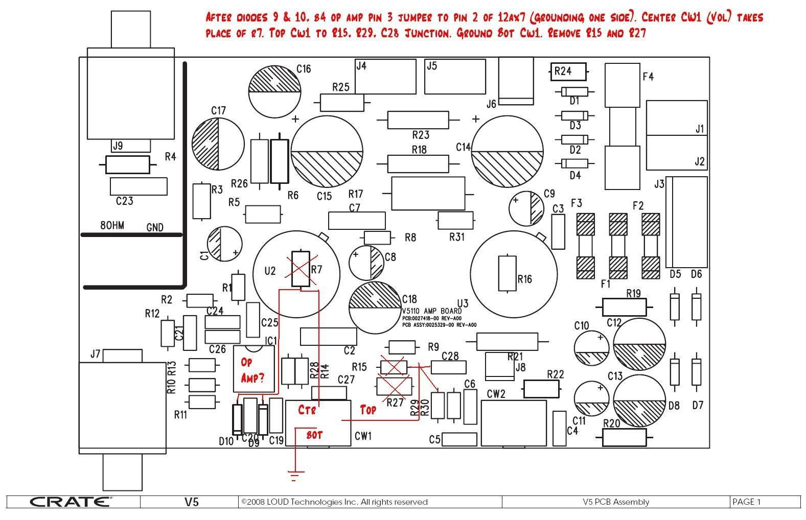
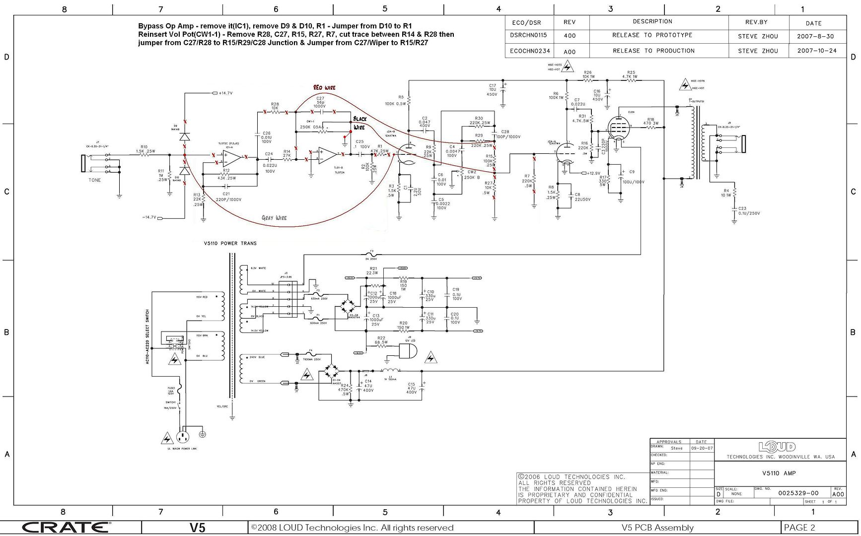
    I looked the mod deafelectromark (manoteal) posted with the schematic and, I think there is a discrepancy? In post 16 talk about the jumper from before the op amp to the first triode stage. In post #97 the actual pin number of the jumper is mentioned as pin 2. Looking at the schematic, if it was jumped to pin 2 then there would be nothing connected to pin 7 of the preamp tube. My guess is that the actual connection should be to pin 7? There is also mention of grounding one end of the coax... is that just the shielding or the core too?

    I have no electrical experience so I am asking the people who are in the know to help on this one. Timothy

    PS: below is deafelectromark's posts that apply here. I have also tried to link the schematic with my best guess of the mod.

    Quote Originally Posted by deafelectromark
    Post #16
    After the input resistors (1.5Kohm and 1 Meg) I cut that trace going to the input of the op amp and sent it straight to the first tube grid and cut away any other parts that were there that might have influence. Since I now had a 250Kohm volume pot out of the circuit, I put that between the tone circuits and the grid to the second triode in place of the attenuation scheme that was there and to maintain grid to ground loading and control. I cut the traces around the volume pot and ran jumpers to the appropriate places (the pot connects to the output of the tone circuit, the two lower resistors were cut out, and the other end of the pot was run to ground. The wiper fed the second triode's grid.
    Deafelectromark (alias manoteal)

    Post #97
    Begin by cutting the trace after the input jack leaving R10,R11 for input loading. This will be just before pin 3 of op amp. Run a short length of coax from there to pin 2 of the 12AX7, and ground this wire at only one end (to prevent ground loops).
    You will be cutting the volume pot out of the circuit and reroute wires as follows-keep the tone control circuit for now).
    Connect the middle wiper to pin 2 of 12AX7. Cut out the R7, 220K resistor and the pot will take it's place for the load and volume control BETWEEN the two 12AX7 halves (this is so your guitar and/or you stompbox can play clean into the preamp tube or to push it more into output stage distortion)
    Connect the top of the control to the junction of R15, R29,and C28: and the bottom to ground. Cut out the 100K (R15) (or R27, 10K) Resistor(s) so that the second half of the preamp tube is driving the same load. So you are basically removing R15, R27 and R7.


  15. #205
    Join Date
    Dec 2008
    Posts
    21
    Post Thanks / Like

    Default Stuupid mistakes

    [QUOTE=timothymegg]I looked the mod deafelectromark (manoteal) posted with the schematic and, I think there is a discrepancy? In post 16 talk about the jumper from before the op amp to the first triode stage. In post #97 the actual pin number of the jumper is mentioned as pin 2. Looking at the schematic, if it was jumped to pin 2 then there would be nothing connected to pin 7 of the preamp tube. My guess is that the actual connection should be to pin 7? There is also mention of grounding one end of the coax... is that just the shielding or the core too?

    I have no electrical experience so I am asking the people who are in the know to help on this one. Timothy

    PS: below is deafelectromark's posts that apply here. I have also tried to link the schematic with my best guess of the mod.

    You are right. : The second half of the preamp tube's input is pin 2 on the schematic and not pin 7. Pin 7 is the input to the first half of the triode (from the guitar jack and as shown in the schematic). I will have to pull my board and look at it again to see what I did. Sometimes I think that lower numbers come first (hence the confusion about pin 2 and 7) Remember that tubes pins are clockwise from the bottom after the space and not from the top- I made this transcription error late at night and pretty groggy. My apologies to all that have tried this and it didn't work for them.
    I will double check my work (three happy customers right now for the boards that I made for them), so I just made a mistake in that post. I will post again with the right information.
    In reference to shielded wire (coax), the coax is not really needed (I didn't have problems with it or without it- it is such a short run) but if you do use coax only ground one end of it (I prefer the input side coming from the input jack ground) for reduced ground loop problems. The middle conductor (not the braid, is for running a connection past the opamp to the input pin of the tube's first section (pin 7). It is always the braided part that is connected to ground (at only one end).
    Does that make sense?

    Thanks for catching that Timothy. I was just seeing if anyone was awake!

    Mark
    Last edited by deafelectromark; May 13th, 2009 at 12:49 PM. Reason: spelling

  16. #206
    Join Date
    Feb 2009
    Posts
    35
    Post Thanks / Like

    Default

    Quote Originally Posted by timothymegg
    I have also tried to link the schematic with my best guess of the mod.
    I haven't done the v5 mod, but I think you want to either cut the trace after R11 before the diodes, or pull R10 leg and move R11 up front where it should be and connect from R10 leg to the tube input. If you pull R1, then you would just run the jumper to the tube side R1 hole. (maybe these pictures will work? WOW, guess I got carried away in making them small, maybe better now...)

    http://i615.photobucket.com/albums/t...pampbypass.jpg

    http://i615.photobucket.com/albums/t...nputreturn.jpg
    Last edited by SciHi; May 14th, 2009 at 05:43 PM.

  17. #207
    Join Date
    Mar 2009
    Posts
    17
    Post Thanks / Like

    Default Lookin good

    Ok, I got some pictures of deafelectromark's mod and so, I think I finally have it how he did the mod on the schematic and his pictures of the board.


  18. #208
    Join Date
    Mar 2009
    Posts
    17
    Post Thanks / Like

    Default

    Quote Originally Posted by SciHi
    pull R10 leg and move R11 up front where it should be
    I'm curious why R11 should be upfront? What does that do? and what does having the way it is change anything?

  19. #209
    Join Date
    Jan 2009
    Posts
    357
    Post Thanks / Like

    Default schematic error in post #207

    Caution the schematic mark up of the volume pot in post #207 is wrong. Where it shows the red wire connected on the pot should be where the pot should be grounded. Then the red wire should be connected on the side of the pot that used to be connected to pin 7 of the op amp. The little dot on the schematic symbol is probably indication of clock wise direction so at full clock wise you want the wiper of the pot at the R29 side(when mod completed). There is also a cut not shown on the schematic the wiper needs to be cut free from the other terminal of the pot. If you leave R1 in this will give you some feedback for high frequencies on the input triode and if over driving the input to amp sounded shrill it would give a plate to grid feedback cap something to work against. The diodes are a few Pico farads the guitar cable is more capacitance then they are so no big need to remove them they were in there to protect the op amp input so your choice. The location of the 1 Meg to ground is not that critical the difference in distance is what an inch or so this is inside of a shielded enclosure and these are audio frequencies. If you remove the op amp C25 and R2 all you need to do is run a jumper from the feedthrough hole of pin 3 of the op amp to feedthrough hole of C25 or R2 to connect input signal to first stage.

Page 11 of 25 FirstFirst ... 91011121321 ... LastLast

Posting Permissions

  • You may not post new threads
  • You may not post replies
  • You may not post attachments
  • You may not edit your posts
  •