Warning: preg_replace(): The /e modifier is deprecated, use preg_replace_callback instead in ..../includes/class_bbcode.php on line 2958
Crate V5 mods... anyone? - Page 2
Page 2 of 25 FirstFirst 123412 ... LastLast
Results 20 to 38 of 465

Thread: Crate V5 mods... anyone?

  1. #20
    Join Date
    Sep 2005
    Location
    Jensen Beach, Florida
    Posts
    2,145
    Post Thanks / Like

    Default

    Quote Originally Posted by Tarin
    Yep, i'm one of those who fell for the Crate V-Series blowout sale, at first i bought the V-18, and considered it a good amp, great for the price... sold it after a great offer made to me.
    Went back to MF only to find out they were out of stock (also in GC, Sameday, Samash and everywhere).
    Made my homework on the V5, and althought it had bad reviews i went for it thinking "how bad could it be" and "even if it's that bad, somebody will come out with mods for it".

    Well, the amp sounds pretty bad (not as bad as the reviews claim, once the cheapo speaker breaks in you get decent tones, that and an EQ pedal), and as of now nobody has come out with a mod for it.

    I got in touch with an Ebay seller who has one "Modded Crate V5" on sale but he asks 230 bucks for it and doesn't sell any mod kit for it (he claims modding this amp consists on almost building an entire new circuit).

    I'm sure i'm not the only one stuck with a V5 waiting for mods... any help?
    Try going over to www.sewatt.com and sign up. There's a new Crate 5 watt discussion just starting there. There's not much info yet, but it may generate some. There's not a whole lot of love there for the Crate 5 watt circuit, so be forewarned. It might need darn near a whole new circuit...

    EDIT TO ADD: I see our new member deafelectro has already been in the Crate discussion on sewatt.co as his alter ego Manoteal...I thought his post here looked familiar...
    Last edited by Bloozcat; December 12th, 2008 at 02:17 PM.

  2. #21
    Join Date
    Nov 2008
    Location
    Tijuana, Mexico
    Posts
    95
    Post Thanks / Like

    Default

    Now back to the main concern: upgrading the V5.

    Deafelectro... That's some great task you've acomplished in the little amp. i might catch you up on sending the board to get modded and be the first one to review and experiment with your findings.
    I already got your email so i'll get in touch with you next week to make this happen.
    Now for the speaker issue... is there any way of including one of your leftover Eminence's in the picture?

    Gretsch Corvette
    Parker P-38
    Yamaha APX500
    Vox Pathfinder 15R
    Vox Tonelab ST
    Blackheart LG
    ... That's it.

  3. #22
    Join Date
    Dec 2008
    Posts
    21
    Post Thanks / Like

    Default Myspace message failure

    Quote Originally Posted by Tarin
    Hello mark, mexican buddy here.
    Just read your bio and can't manage to clos my jaw... that must be the shortest/best explained/interesting and surprising bio i've read in a long time (people at Myspace could learn how to get a message thru).
    Thanks C.
    Your last line is cryptic- what do you mean concerning Myspace? That they can't speak succinctly? It is a skill after all. I do become quite long winded (see first post above), but last night you (and the rest of us) got lucky. I was passing out from lack of sleep. I just HAD to say what I said. That said- let the music begin!
    M

  4. #23
    Join Date
    Jan 2009
    Posts
    357
    Post Thanks / Like

    Default crate v5 mods

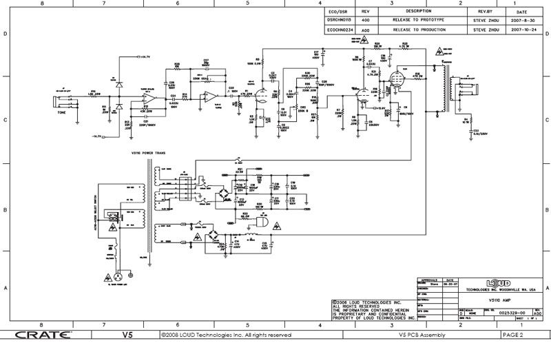
    I bought a V5 from Musicians Friend for 80 bucks and have started modifying it. I have two Epi valve Jr. Amps one that I added reverb, triode pentode switch, and Alnico Weber speaker to and the other with FET input high voltage regulator and 6V6 installed. I saw the schematics for the V5 on the web and can see right away they have an amplifier with a solid state preamp (TL072) and tube output not what most people want but easy to fix. Getting the amp found the stock speaker is probably not a guitar speaker so first thing was playing it through the valve Jr speakers also a pair of Jensen 10 special designs made a big difference. So ordered a new speaker from Ted Webber (they have 15% off right now so 43 bucks total with shipping) they make the stock speaker in the old valve Jr. I think. For circuit mods so far I did not remove the Op Amp because it is used for high frequency bypass (above 100Hz) and pre emphasis (boost the highs so the tone control can take them out or pass them through). So I removed R13 to change IC1-A to unity gain and use as a high impedance buffer to not load down the guitar pickups. Next removed C26 changed C24 to 47nF (Note this should be 100nF) removed C27 and installed a 33k resistor in its place removed the 250k pot to use as a volume control after the tone stack. Lifted the 100nf C25 at the node connecting it to R2 and R1 putting a 33k resistor with a 10 nF cap accost it in series (this is now the pre emphasis for the tone stack) With these changes if you over drive the amplifier input with overdrive instead of the OP Amp clipping (awful noise) the first stage tube will clip (as man and god intended when tube amps were created) Next on the tone control changed C6 to 25 nF removed C5 (not sure where a frequency this high is going to come from) and removed C4 (so when you turn the tone control all the way up it does not go to no highs) Now to install the volume pot removed R15 and R27 connected the 250K pot CW1 that was in the Op Amp feedback to ground on the wiper full CCW side connected the wiper to junction of R15, R27, R7 and the grid of J2-A and the third terminal of the pot to junction of R29 C28. Now the tone is set to flat at a quarter turn (9 o’clock position). Then checked the output of the amplifier with a frequency generator and scope and found that it did not clip equally at high volume and started to oscillate. Fixed that by lowering the cathode bias resistor to what the data sheets call out for 270 ohms. Also changed R22 the resistor in series with the power indicator to 150 ohms but it is still to bright will probably go to 220 ohms also it is a light bulb not an LED.
    As always if you do mods to a tube amplifier be careful of the high voltages in this case a plate voltage of 316 volts. There is a bleeder resistor R24 so that helps but use a volt meter. And always remember the one hand rule do all your probing with one hand make sure no other part of your body or your other hand is tied to ground.
    I changed the value of C24 above found lowest frequency from guitar to be 82Hz not 190Hz.
    Last edited by jim p; May 4th, 2009 at 04:14 PM.

  5. #24
    Join Date
    Nov 2008
    Location
    Tijuana, Mexico
    Posts
    95
    Post Thanks / Like

    Default

    Wow, that's some major modding. Unlike what Deafelectro achieved with his more simple mods.
    I've been in touch with Deafelectro for him modding my V5 since he's is the only mod i've come up in the internet.
    But now that you have accomplish another one...it's only fair to take in consideration, any clips? pics?

    Gretsch Corvette
    Parker P-38
    Yamaha APX500
    Vox Pathfinder 15R
    Vox Tonelab ST
    Blackheart LG
    ... That's it.

  6. #25
    Join Date
    Jan 2009
    Posts
    357
    Post Thanks / Like

    Default Re: Crate V5 mods

    I have no pictures or sound clips right now. Would like to post a marked up schematic if I get a chance maybe pics. It sounds like a lot of mods but it’s not really but maybe that is because I am an electronic engineer in analog design. I did all the mods with no cuts to the PC board I did have to attach wires to the volume pot to connect it the pc board and add electrical tape under it to prevent a short to the board. All the other mods except the pre emphasis mod (33k ohm with 10nF in parallel between C25 and R1, R2) are removing components and leaving them out, changing there value or in the case of C27 replacing it with a resistor. At the least I would change R17 to 180 ohms to stop the oscillation in the EL84 output tube I just paralleled it with another 330 ohm 2 watt (165 ohms) as a quick modification. With the Op Amp input I just wanted to use it as a buffer circuit with minimum gain (equal to loss in pre emphasis circuit) so if you overdrive you will clip the first stage tube. I was hoping that I could fit a set of dual concentric pots in place of the two pots so I would have gain, tone, volume and reverb controls on the front panel. I am going to add reverb using a Ruby tank from a Crate V33 head that I changed to an Accutronics 3 spring tank. Will probably change the output tube to a 6V6 this is for my son as a practice amplifier he likes Fender amps with reverb. Good chance will need a triode/pentode switch also. I have modified the Crate V33 head and a Crate V50 and have a V18 (will change to 6V6 output class AB) on order like fooling with tubes and these are so cheep for what you get. You have to remember it is hard to kill a tube (as long as it is cathode biased) unlike transistors, fets and ICs. If you do something wrong will probably just get no sound out.
    Last edited by jim p; February 7th, 2009 at 10:30 AM.

  7. #26
    Join Date
    Jan 2009
    Posts
    357
    Post Thanks / Like

    Default Re: Crate V5 mods

    I have attached pictures of mods and sections of schematic where changes were made. I may do a step by step explanation of the modifications in the future.
    Error value of C24 should be 100nF not 47nF found lowest frequency from guitar is 82Hz not 190Hz.
    Last edited by jim p; May 4th, 2009 at 04:18 PM.

  8. #27
    Join Date
    Feb 2009
    Location
    Location: Location
    Posts
    29
    Post Thanks / Like

    Default

    Quote Originally Posted by Tarin

    Can you please post this at a higher resolution, or maybe link as a pdf. When
    trying to magnify, all it does is blur.

    Thanx,--- Dave

  9. #28
    Join Date
    Nov 2008
    Location
    Tijuana, Mexico
    Posts
    95
    Post Thanks / Like

    Default

    Crate V5 schematics

    Gretsch Corvette
    Parker P-38
    Yamaha APX500
    Vox Pathfinder 15R
    Vox Tonelab ST
    Blackheart LG
    ... That's it.

  10. #29
    Join Date
    Nov 2008
    Location
    Tijuana, Mexico
    Posts
    95
    Post Thanks / Like

    Default

    Jim_P... thanks a lot, i'll take a look at what you've done and maybe i'll do thos mods to mine, although a step by step will help a lot.

    I'm pretty sure that this thread is gonna recieve lots a visits cause i know theres a lot of people waiting for a DIY mod for this little amp.

    I have some pics of what Deafelectro did to his and it's different from what you did... i would like to post them but, i'll need deafelectro's permission for that.

    Gretsch Corvette
    Parker P-38
    Yamaha APX500
    Vox Pathfinder 15R
    Vox Tonelab ST
    Blackheart LG
    ... That's it.

  11. #30
    Join Date
    Feb 2009
    Location
    Location: Location
    Posts
    29
    Post Thanks / Like

    Default

    Quote Originally Posted by Tarin
    Crate V5 schematics
    Thnx for schem.........Dave
    _____________________________________________

    "Whoa Mule! Whoa!---When I say Whoa, I Mean Whoa!!!!!!

  12. #31
    Join Date
    Feb 2009
    Location
    Location: Location
    Posts
    29
    Post Thanks / Like

    Default

    Quote Originally Posted by jim p
    Would like to post a marked up schematic...............

    Please Do. looks like a good mod.
    _____________________________________________

    "Whoa Mule! Whoa!---When I say Whoa, I Mean Whoa!!!!!!

  13. #32
    Join Date
    Jan 2009
    Posts
    357
    Post Thanks / Like

    Default Step by step modifications done to Crate V5 amp

    Step by step modifications done to Crate V5 amp

    1) Remove the amplifier from cabinet. First remove speaker jack then the six screws holding back cover of amplifier then with amplifier upside down remove four screws two on each side of cabinet that hold amplifier chassis in cabinet. (Note: you may want to enlarge the holes slightly in sides of cabinet and on back cover to make reinstallation and future removal easier)

    2) If you haven’t already done so (you do have this unplugged right?) get out a dc voltmeter the highest voltage in the amplifier is approx. 320 volts DC measure from chassis to R25 should be 0 to 15 volts if so you are safe. This amplifier has a bleeder resistor R25 so supplies should drop after power down.


    3) Remove preamp (12AX7) and power tube (EL84 6BQ5) put them some where you wont break them.

    4) Next remove knobs on front panel may require flat blade screwdriver and a thin piece of wood to work against to prevent scratching front panel. The pots are D shaft type walk then off gently. Then remove nuts holding pots and ¼ inch jack on front panel.


    5) Now make note of all the connections to the PC board because you are going to remove them. If you have a digital camera now is a good time to use it. Also if you print out the schematic note wire color and location on it. The faston connectors J4 J5 J1 and J2 may be hard to remove don’t break them of pcb by working them back and fourth.

    6) Next remove the six screws that hold PCB into chassis and take it out. (hope you are putting parts someplace you wont loose them)

    PC Board modifications
    (See attached pictures of mods and changes to schematic also pic DSCF0947.jpg in previous post is the pre emphasis mod the tone mod is incorrect in that post tie unused side of pot in tone control to wiper not ground or unconnected up to you)

    1) You are going to be removing approx 10 parts. You will need solder, solder wick, soldering iron, needle nose pliers and desoldering tool. In manufacture the compnet leads have been bent so desolder a componet lead then straighten it before removing or you may damage PCB plated feedthrough.

    2) This modification will use the two Op Amp stages for an input buffer and small gain to over come loss due to pre emphasis circuit that will be added. Desolder and remove volume pot from PCB. Next remove R13 this makes IC1-A a unity gain buffer. Remove C26, C24 and C27 replace C24 with a 47nF 50-100 volt poly cap.C24 sets the low frequency limit at input to the amplifier with 47nF this is approx 125 HZ 3db down (for more bass use 100nF). In the place of C27 install a 33k ¼ watt resistor this equals a gain of 1.22 for IC1-B (want to keep gain low so first stage tube will clip before the Op Amp with overdrive).
    ERROR Value of C24 should be 100nF lowest frequency from guitar is 82Hz.


    3) Pre emphasis circuit For the tone control to be able to cut, boost and be set for flat response the high frequencies need to be boosted first. So C25 needs to be removed if you want replaced or use it again for this mod. Install one lead of a 100nF 50-100 volt cap into plated hole (via) that is connected to pin 7 of IC1 in the second hole of C25 insert lead of 33k ohm ¼ watt resistor with a 10nf capacitor accost it then connect the other lead of the 33k resistor to the second lead of the 100nF capacitor. If you want full treble brighter you can lower value of R2

    4) Tone stack and volume control Here we will put volume control after tone stack and first tube stage so you will be able to overdrive input tube and still control volume. Remove C5 C6 C28 and C4 Change C6 to a 22nF 50-100volt poly capacitor. (Here a lower value cap will raise where the tone control will cut the highs higher value will lower it.) Now the volume control remove R15 and R27 using the volume pot removed from the board you will need to bend the leads 90 degrees towards the back of the pot to attach 1 ½ inch wires to the three terminals of the pot. Also need to insulate PCB were pot was attached to prevent shorting (three layers of electrical tape works) looking at the front of the pot as use to be connected to the PCB the right side terminal connects to the plated hole C28 that connects to R29 the center terminal (wiper) connects to the plated hole of R27 that connects to R7 and control grid (pin 2) of the 12AX7. The last terminal goes to the plated hole of R27 that goes to ground. (note be careful the leads soldered to pot do not short to metal back shell of pot no sound out of amp)

    5) Oscillating power tube in testing the amplifier found output did not clip symmetrically and oscillated when clipped. Based on the tube data sheets the cathode biasing is to high in value. Change R17 to 270-300 ohms 2-5 watt or parallel the 330 5 watt with another 1.5k ohm 2 watt (270 ohms)


    6) That’s it now put it back together and be careful around high voltage always follow one hand rule working on tube amplifiers. The one hand rule is make sure other hand and body are not tied to ground other hand does all the probing. So tie meter or scope ground to the chassis ground then do all your measurements.

    Other tweaks
    From the way this amplifier is set up it may have had gain, tone and volume controls?
    And they took the volume control out instead of the gain control so if you add a third 250k pot across TL01-B same as in the stock schematic this will be a gain control you should add a 27k resistor in series to set minimum gain at unity (1).

    Lowest frequency amplified the stock value of C24 is to low 3db down at approx 270Hz the value in the mod is 47nF for 125Hz if you want you can go bigger 100nF but this may increase that annoying 60 Hz hum we have all come to love.
    ERROR Should go with 100nF lowest frequency from guitar is 82Hz

    On the pre emphasis mod you can change the value of R2 to increase or decrease the brightness of the maximum tone. Higher value for R2 (stock 100k) will reduce the maximum lower value increase it. If you lower the value you may want to increase the gain in the Op Amp stage to offset the loss.

    Tone control pot from my results the tone is flat at the 9 o’clock position so if you use a 100k (125K) pot for the tone control this will move it to the 12 o’clock position.
    Changing where the tone control operates you can reduce the value of C6 to raise or lower where the tone control operates but you should change the value of the cap in the pre emphasis circuit also (10nF across 33k ohm).
    Last edited by jim p; May 4th, 2009 at 04:22 PM.

  14. #33
    Join Date
    Jun 2007
    Location
    Westminster, Colorado
    Posts
    2,203
    Post Thanks / Like

    Default

    Cool, thanks for posting that. The Best Buy near me has these for $100, I may have to pick one up and try the mods.

    Have you tried adding additional capacitance to kill some of the 60hz hum?

    tung


    Quote Originally Posted by jim p
    Step by step modifications done to Crate V5 amp

    1) Remove the amplifier from cabinet. First remove speaker jack then the six screws holding back cover of amplifier then with amplifier upside down remove four screws two on each side of cabinet that hold amplifier chassis in cabinet. (Note: you may want to enlarge the holes slightly in sides of cabinet and on back cover to make reinstallation and future removal easier)

    2) If you haven’t already done so (you do have this unplugged right?) get out a dc voltmeter the highest voltage in the amplifier is approx. 320 volts DC measure from chassis to R25 should be 0 to 15 volts if so you are safe. This amplifier has a bleeder resistor R25 so supplies should drop after power down.


    3) Remove preamp (12AX7) and power tube (EL84 6BQ5) put them some where you wont break them.

    4) Next remove knobs on front panel may require flat blade screwdriver and a thin piece of wood to work against to prevent scratching front panel. The pots are D shaft type walk then off gently. Then remove nuts holding pots and ¼ inch jack on front panel.


    5) Now make note of all the connections to the PC board because you are going to remove them. If you have a digital camera now is a good time to use it. Also if you print out the schematic note wire color and location on it. The faston connectors J4 J5 J1 and J2 may be hard to remove don’t break them of pcb by working them back and fourth.

    6) Next remove the six screws that hold PCB into chassis and take it out. (hope you are putting parts someplace you wont loose them)

    PC Board modifications
    (See attached pictures of mods and changes to schematic also pic DSCF0947.jpg in previous post is the pre emphasis mod the tone mod is incorrect in that post tie unused side of pot in tone control to wiper not ground or unconnected up to you)

    1) You are going to be removing approx 10 parts. You will need solder, solder wick, soldering iron, needle nose pliers and desoldering tool. In manufacture the compnet leads have been bent so desolder a componet lead then straighten it before removing or you may damage PCB plated feedthrough.

    2) This modification will use the two Op Amp stages for an input buffer and small gain to over come loss due to pre emphasis circuit that will be added. Desolder and remove volume pot from PCB. Next remove R13 this makes IC1-A a unity gain buffer. Remove C26, C24 and C27 replace C24 with a 47nF 50-100 volt poly cap.C24 sets the low frequency limit at input to the amplifier with 47nF this is approx 125 HZ 3db down (for more bass use 100nF). In the place of C27 install a 33k ¼ watt resistor this equals a gain of 1.22 for IC1-B (want to keep gain low so first stage tube will clip before the Op Amp with overdrive).


    3) Pre emphasis circuit For the tone control to be able to cut, boost and be set for flat response the high frequencies need to be boosted first. So C25 needs to be removed if you want replaced or use it again for this mod. Install one lead of a 100nF 50-100 volt cap into plated hole (via) that is connected to pin 7 of IC1 in the second hole of C25 insert lead of 33k ohm ¼ watt resistor with a 10nf capacitor accost it then connect the other lead of the 33k resistor to the second lead of the 100nF capacitor. If you want full treble brighter you can lower value of R2

    4) Tone stack and volume control Here we will put volume control after tone stack and first tube stage so you will be able to overdrive input tube and still control volume. Remove C5 C6 C28 and C4 Change C6 to a 22nF 50-100volt poly capacitor. (Here a lower value cap will raise where the tone control will cut the highs higher value will lower it.) Now the volume control remove R15 and R27 using the volume pot removed from the board you will need to bend the leads 90 degrees towards the back of the pot to attach 1 ½ inch wires to the three terminals of the pot. Also need to insulate PCB were pot was attached to prevent shorting (three layers of electrical tape works) looking at the front of the pot as use to be connected to the PCB the right side terminal connects to the plated hole C28 that connects to R29 the center terminal (wiper) connects to the plated hole of R27 that connects to R7 and control grid (pin 2) of the 12AX7. The last terminal goes to the plated hole of R27 that goes to ground. (note be careful the leads soldered to pot do not short to metal back shell of pot no sound out of amp)

    5) Oscillating power tube in testing the amplifier found output did not clip symmetrically and oscillated when clipped. Based on the tube data sheets the cathode biasing is to high in value. Change R17 to 180 ohms 2-5 watt or parallel the 330 5 watt with another 330 ohm 2 watt (165 ohms)


    6) That’s it now put it back together and be careful around high voltage always follow one hand rule working on tube amplifiers. The one hand rule is make sure other hand and body are not tied to ground other hand does all the probing. So tie meter or scope ground to the chassis ground then do all your measurements.

    Other tweaks
    From the way this amplifier is set up it may have had gain, tone and volume controls?
    And they took the volume control out instead of the gain control so if you add a third 250k pot across TL01-B same as in the stock schematic this will be a gain control you should add a 27k resistor in series to set minimum gain at unity (1).

    Lowest frequency amplified the stock value of C24 is to low 3db down at approx 270Hz the value in the mod is 47nF for 125Hz if you want you can go bigger 100nF but this may increase that annoying 60 Hz hum we have all come to love.

    On the pre emphasis mod you can change the value of R2 to increase or decrease the brightness of the maximum tone. Higher value for R2 (stock 100k) will reduce the maximum lower value increase it. If you lower the value you may want to increase the gain in the Op Amp stage to offset the loss.

    Tone control pot from my results the tone is flat at the 9 o’clock position so if you use a 100k (125K) pot for the tone control this will move it to the 12 o’clock position.
    Changing where the tone control operates you can reduce the value of C6 to raise or lower where the tone control operates but you should change the value of the cap in the pre emphasis circuit also (10nF across 33k ohm).
    I was just a regular guy. My only super power was being invisible to girls.
    - Dave Lizewski, Kick-A$$

  15. #34
    Join Date
    Jan 2009
    Posts
    357
    Post Thanks / Like

    Default the Amplifier is quiet

    When I was talking about 60 Hz hum I meant pick up from the guitar not in the amplifier. The amplifier has 1 H choke pi filter and DC filament voltage on the 12AX7 its quiet compared to the Valve Jr combo I have.

  16. #35
    Join Date
    Jan 2009
    Posts
    357
    Post Thanks / Like

    Default crate V5 with reverb pentode/triode sw Webber spk

    Posted pictures of close to final modification of Crate V5 I bought. The vector board is the reverb drive and recovery amplifiers. Replaced the stock (crap) speaker with a Webber ceramic 10S for 38 bucks with shipping. The reverb tank is a Accutronics box with Ruby OEM guts (2 spring) from a Crate V33H. On the back pannel is the reverb pot and pentode/triode switch. May do a better job of running the RCA lines to reverb in future. I see the Crate V5 is 85 bucks at Best Buy dot com with in store pick up so the shipping is free.

  17. #36
    Join Date
    Feb 2009
    Location
    Location: Location
    Posts
    29
    Post Thanks / Like

    Default

    Quote Originally Posted by jim p
    Posted pictures of close to final modification of Crate V5 I bought. The vector board is the reverb drive and recovery amplifiers. Replaced the stock (crap) speaker with a Webber ceramic 10S for 38 bucks with shipping. The reverb tank is a Accutronics box with Ruby OEM guts (2 spring) from a Crate V33H. On the back pannel is the reverb pot and pentode/triode switch. May do a better job of running the RCA lines to reverb in future. I see the Crate V5 is 85 bucks at Best Buy dot com with in store pick up so the shipping is free.
    Can you post schematic changes and step by step for these mods?

    Question on previous mods. In step 2 of board mods where you remove C26 C24 and C27, C24 and C27 are replaced with other components but C26 is not. Is this left open or is it jumpered? If not jumpered then I assume it is O.K. to remove R28 since it is not connected to anything?

    Also I want to have Gain and Volume setup. Can I just leave existing pot connected in its place on board and use another pot for the volume mod such as you have it? I understand that I will have to lift a leg on pot or cut trace on board to put in 27k resistor in series with pot. Is this right?

    Thnx---Dave
    _____________________________________________

    "Whoa Mule! Whoa!---When I say Whoa, I Mean Whoa!!!!!!

  18. #37
    Join Date
    Jan 2009
    Posts
    357
    Post Thanks / Like

    Default re: R28

    Yes if you want you can remove R28 without C26 it has no function. If you want gain and volume CW1 the 250k pot accost TL01-B can be used as a gain pot. In that case do not install a resistor in the location of C27. You may to set a minimum gain by putting a 10k resistor in series with the 250k gain pot. If you search the web or call Crate for a VC508 schematic this will give you an idea of the gain, tone and volume set-up. I don't like the values of capacitance they used for the 508 also the low supply rails on the op-amp (+7 -7). This amp is better in the fact you have +/- 15 volts (more within limits if you reduce R19 and R20) for the op-amp a 1 Hennery choke in the plate supply and DC filament supply on the 12AX7. Bad thing is they took out the wrong pot to remove the gain function did not change bandwidth for a 10 inch speaker (more bass) and used a crappy speaker.

  19. #38
    Join Date
    Feb 2009
    Location
    Location: Location
    Posts
    29
    Post Thanks / Like

    Default

    Quote Originally Posted by jim p
    Yes if you want you can remove R28 without C26 it has no function. If you want gain and volume CW1 the 250k pot accost TL01-B can be used as a gain pot. In that case do not install a resistor in the location of C27. You may to set a minimum gain by putting a 10k resistor in series with the 250k gain pot. If you search the web or call Crate for a VC508 schematic this will give you an idea of the gain, tone and volume set-up. I don't like the values of capacitance they used for the 508 also the low supply rails on the op-amp (+7 -7). This amp is better in the fact you have +/- 15 volts (more within limits if you reduce R19 and R20) for the op-amp a 1 Hennery choke in the plate supply and DC filament supply on the 12AX7. Bad thing is they took out the wrong pot to remove the gain function did not change bandwidth for a 10 inch speaker (more bass) and used a crappy speaker.
    So no resistor in place of C27. Do I remove C27 or leave it in place?

    Also in step 5 you change R17 to 270ohm 5W, but in tung's post next looks like it was changed to 180ohm 5W. Which one is correct?


    Thnx----Dave
    _____________________________________________

    "Whoa Mule! Whoa!---When I say Whoa, I Mean Whoa!!!!!!

Page 2 of 25 FirstFirst 123412 ... LastLast

Posting Permissions

  • You may not post new threads
  • You may not post replies
  • You may not post attachments
  • You may not edit your posts
  •