


 Reply With Quote
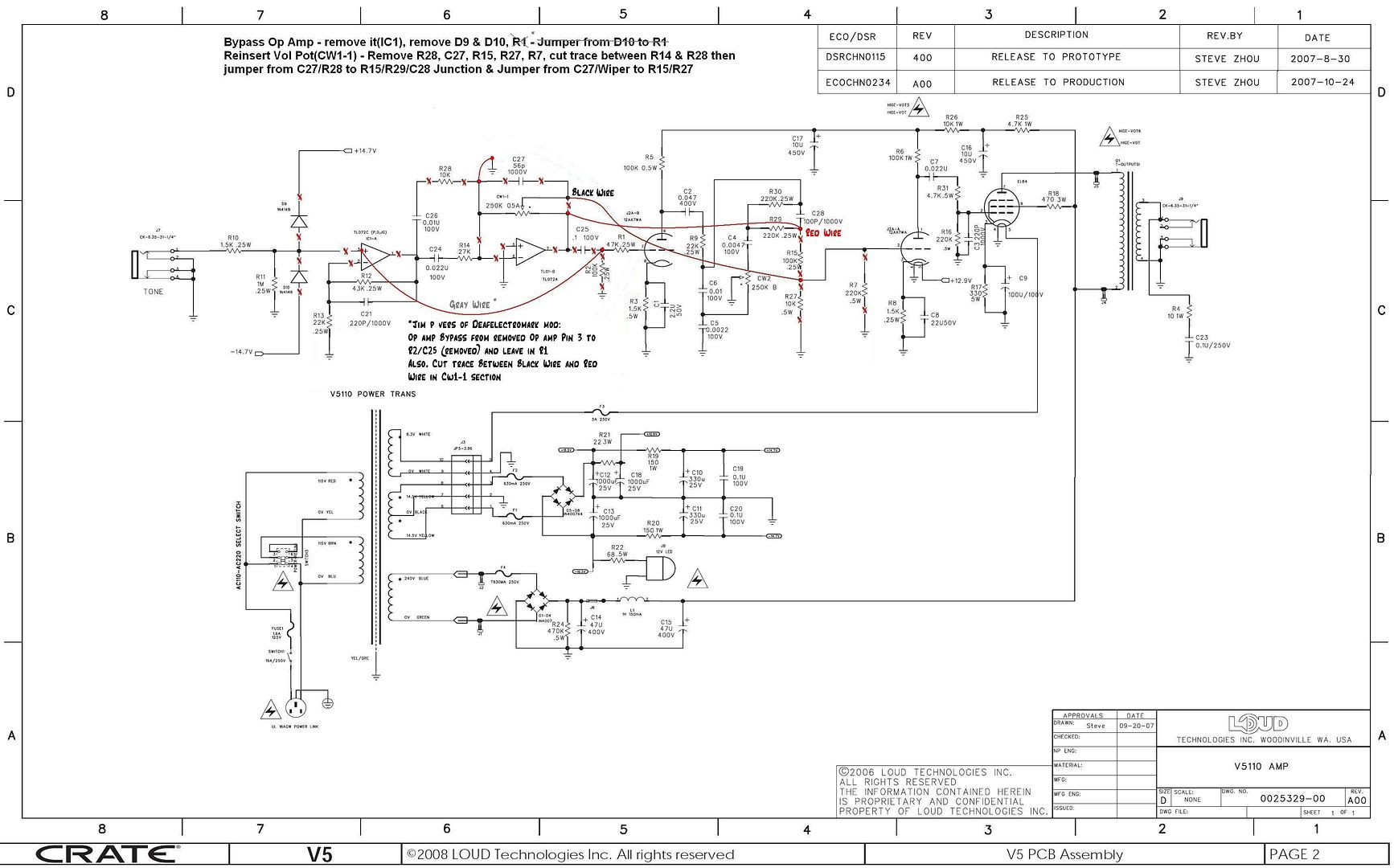
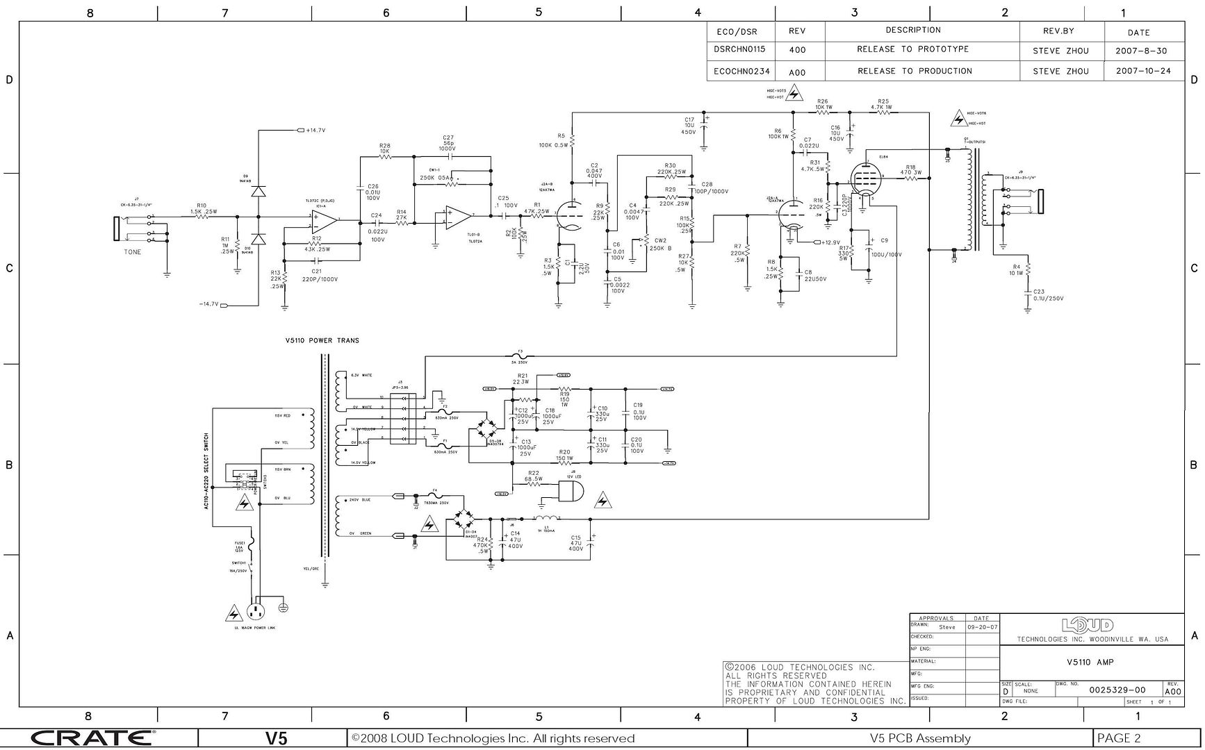
First off I would get a clean copy of the schematic either from a post or Crate. Then go through all the posts here that should give you an idea of what is going on in and with the amplifier. As stated way back this amp by design is a solid state preamp (op amp) with a tube output so not ideal. Also it is based off an amp that had an 8 inch speaker that they limited the bass response on. Most of the parts on the amplifier are good except the speaker, screws and nuts. You have a double sided PCB with plated holes I was just looking inside a Epiphone Valve Jr. that has your chepo single sided no plated holes PCB. You also get that 1 Hennery choke in the power supply, iron being a big expense to a manufacture in cost and shipping weight. So anyway go through the posts and figure what mod makes the most sense for you in terms of skill level and the tone you want. For the most bass response adding feedback will extend bass by lowering output impedance therefore reflected impedance at the primary. Also the triode mode will increase bass response by lowering the tube impedance to 2 K ohms from the pentode mode impedance of 35 to 50 k ohms but with loss of output power 1.5 watts and darker sound.
 Hi all, just a note to say I have installed an 8 ohm Celestion Tube 10 speaker in place of the stock Crate speaker in one of my V5s. Very nice, and heartily recommended: more bottom end, less brittle plasticky high-end, and when in distortion mode, when two notes heterodyne (like on a major third interval) I get this really creamy, warm break-up that sounds frighteningly like Jimmy Page sted of just garbage. And the speaker isn't even broken in yet! My other two V5s will be getting their Tube 10 speakers in the near future.