Warning: preg_replace(): The /e modifier is deprecated, use preg_replace_callback instead in ..../includes/class_bbcode.php on line 2958
Crate V5 mods... anyone? - Page 13
Page 13 of 25 FirstFirst ... 3111213141523 ... LastLast
Results 229 to 247 of 465

Thread: Crate V5 mods... anyone?

  1. #229
    Join Date
    Jun 2007
    Location
    Westminster, Colorado
    Posts
    2,203
    Post Thanks / Like

    Default

    Quote Originally Posted by SciHi
    I think they say ~6.5K can be used for either EL84 or 6v6, but not the best for either. Maybe it is 4-5K for EL84s and 7-8K for 6V6?
    Just a few thoughts from modding Valve Juniors and building tweed Princeton circuits:

    I've used the Hammond 125ESE with both 6V6s and EL84s and it seems to work well using the 5K setting.

    In one Valve Junior rebuild (chassis gutted and rebuilt with an eyelet board and NOS tubes) I used a massive Heyboer OT. It was rated conservatively at 160mA on the primary. It had 2.5k, 4k, and 6k primary impedances. I tried both 4k and 6k for use with the EL84 and 6k sounded best to me.

    I've used a 125CSE in a Valve Junior circuit and I thought it sounded too bright and gritty, the 125ESE was a major improvement to my ears.

    I've probably built over a dozen amps using tweed Princeton circuit and various combinations of tubes. About half were built using the 125ESE and 6V6 tubes. On one amp I substituted an Edcor XSE15-8-5k OT for the Hammond. To my ears the Hammond sounded better when the amp was pushed into distortion. The Edcor sounded better clean.

    FWIW

    tung

  2. #230
    Join Date
    Jun 2009
    Posts
    1
    Post Thanks / Like

    Default Eminence Speaker

    A few pages back, there was some discussion about which speakers will fit in the V5. I just put an eminence Patriot Ragin Cajun in mine and it fit with no problem; which surprised me since I measured everything first and thought that no way it would fit.
    I also put in JJ EL84 and ECC81 while I had it apart.
    Noticeable improvement in sound especially with my overdrive and distortion pedals. The stock speaker sounded like an angry can of bees, the Eminence sounds, well, like a speaker should sound.
    I also plugged the V5 into my Deluxe Reverb cabinet with a Weber 12F150; The 12" speaker has some better warmth, but, considering that the Weber cost more than the whole V5 amp (I got mine at BestBuy for $50) i think the V5 is just fine. I might improve the board if I get brave enough, or just ship it to Mark Deafelectro because he is cool.

    Mike

  3. #231
    Join Date
    Feb 2009
    Posts
    35
    Post Thanks / Like

    Default

    Quote Originally Posted by jim p
    The secondary to primary load for the Crate is
    4 ohms : 1600 ohms
    8 ohms : 3200 ohms
    16 ohms : 6400 ohms
    ...
    Jim, on the 6v6 mod earlier, http://www.thefret.net/showpost.php?...6&postcount=58, did you stick with the stock v5 OT? Are you saying running a 16 ohm speaker will make the OT more 6v6 friendly? How did that 6v6 mod turn out? As you say with the extra heater capacity you could power another preamp tube for a cascaded preamp, similar to the new Plexi Junior SE build.

  4. #232
    Join Date
    Jan 2009
    Posts
    357
    Post Thanks / Like

    Default RE output power and 6V6 mod

    What I was getting at with a 16 ohm load you won’t loose the watts at the output you are with an 8 ohm load. Power is equal to current squared times impedance (resistance) so do to the fact that with 8 ohms you are only 3200 ohms reflected instead of 5000 you are loosing power. While with 16 ohms you would have 6400 reflected and not have the loss. I don’t know about the whole 7k is better with this tube 5k with that thing I used the stock transformer with the 6V6 tube when I moded that amp. As I stated the heater current is less for a 6V6 by a factor equal to the current required for a 12AX7 so I may add a third tube to the third amp I have. But I may go with a signal pentode that I will overdrive before the output to see how that works.
    I am thinking of dropping the plate supply on the V5 to up the plate current so it might give you greater output power with the stock transformer. But first I need to replace the stock (junk) output transformer on a VJ combo ver 1 amp and may give the ultra-linear mode a try with that.

  5. #233
    Join Date
    Feb 2009
    Posts
    35
    Post Thanks / Like

    Default

    Quote Originally Posted by jim p
    As I stated the heater current is less for a 6V6 by a factor equal to the current required for a 12AX7 so I may add a third tube to the third amp I have...
    So we aren't running the opamp, so can we gain enough current from the existing 12.9 volt preamp heater circuit to run the second preamp tube ? The PT has 6.3 volt for the EL84 separate from the opamp and preamp heaters (+14.5,0,-14.5).

  6. #234
    Join Date
    Feb 2009
    Posts
    35
    Post Thanks / Like

    Default

    Quote Originally Posted by jim p
    ...I used the stock transformer with the 6V6 tube ...
    So the stock setup has R4-C23, Zobel (?) network, across the output to the speaker. So isn't this to correct an issue between the speaker and OT? So is the problem with the speaker or OT?

    When you do your variable nfb you mentioned over on SEWATT, do you just connect at R4?

  7. #235
    Join Date
    Jan 2009
    Posts
    357
    Post Thanks / Like

    Default Re: feedback and third tube

    That RC network (R4, C23) on the secondary of the output transformer by my calculation doesn’t do anything till approx 160 kHz so don’t know the point in it. As far as variable negative feedback check post #201 I have a schematic and description of how to do it there.

    Regarding heater current I was going to hook up the third tube to the 6.3 volt AC heater supply. I am running a tacked in 6CB6 pentode to try things out as far as adding a pentode for overdrive with the stock EL 84 and so far no problems. If things work out will switch to an EF86 for the pentode (wish they were cheaper). The heater supply is on the high side (should be 6.3 volts +/- 5%) so in future may look into adding a resistor in series.

    Removing the op amp only frees up 10mA of current at best if you were going to use the +/- 15 volt supply for heater current. If I used one of those supplies I would go with the -15 to balance the load on the secondary. I see at Sewatt that they look to be adding all kinds of loads on the stock VJ transformer I wonder how they determined that the transformer is ok with the added loads?

  8. #236
    Join Date
    Feb 2009
    Posts
    35
    Post Thanks / Like

    Default

    Quote Originally Posted by jim p
    As far as variable negative feedback check post #201 I have a schematic and description of how to do it there.
    Thanks. The schematic posted at SEWATT has the pot on the ground side of the the cathode bypass cap (cap needs lifted for nfb to work). I think that is correct, not as shown in the schematic in post #201???

  9. #237
    Join Date
    Feb 2009
    Posts
    35
    Post Thanks / Like

    Default cheaper pentode?

    Quote Originally Posted by jim p
    If things work out will switch to an EF86 for the pentode (wish they were cheaper).
    Has anyone tried the Russian tube equivalents? " NOS RUSSIAN tubes (6J32P)/6267/EF86 " We have had good results with some of the Russian EL84M's.

  10. #238
    Join Date
    Feb 2009
    Posts
    35
    Post Thanks / Like

    Default

    Quote Originally Posted by jim p
    What I was getting at with a 16 ohm load you won’t loose the watts at the output you are with an 8 ohm load...
    Jim, I think you really have something here! So I hooked up to my 2-12 cab, 2 - 16 ohm speakers in parallel. Put one on a switch so I could go from 2-12 at 8 ohms to 1-12 at 16 ohms (Jensen mod 12-70). Sounds much, much better with the single 16 ohm speaker, clearer, fuller (bottom end), and louder!!! I will have to try the reverse with 2 - 8 ohm speakers hooked up in series to really nail this one.

    OK, just tried it with 2 - 8 ohm 10's in series. Sounds better at 16 ohms. So I think I will shop around and try to find a mod 10 in 16 ohm, I checked out the weber sig 10s and they are only available in 8 ohm.

    So what's the downside with the 16 ohm load, is it harder on the EL84? (nothing died yet)
    Last edited by SciHi; June 16th, 2009 at 09:52 AM.

  11. #239
    Join Date
    Jan 2009
    Posts
    357
    Post Thanks / Like

    Default Re: SciHi posts

    In the schematic for the negative feed back there is an X through the cap not to clear in the picture. Removing it is also in the text describing the mod. As far as the order of cap and pot and which is tied to ground doesn’t matter much.

    On rethinking if the pot is at ground then the wires to the pot will be a twisted pair with one lead at ground so may be better for noise reduction wired with pot at ground.

    I figure to go with the EF86 pentode because it looks to be an available standard part now, plus the mesh screen inside of the tube looks cool. If the pin out of the EL84 is the same I might look for that.

    On to a 16 ohm load on the amp I don’t see that it should be a problem the primary impedance will be 6400 ohms instead of the standard 5000 ohms which should not be too bad. I forget where the plate voltage is at this point but at most may pay to keep it at approx 300 volts but without scoping it out that is just speculation.
    Last edited by jim p; June 15th, 2009 at 06:41 AM.

  12. #240
    Join Date
    Mar 2009
    Posts
    17
    Post Thanks / Like

    Question Tone Stack seems to do VERY little

    Quote Originally Posted by jim p
    Post #168: No OP Amp, No Jumper Mod...

    Options:
    Short R30 or R29 and remove C28 for more maximum signal at grid of second triode.
    Replace loss of pre emphasis for tone stack by replacing C1 with a 200nf cap so tone control will be treble boost, flat and treble cut. Or instead change R9 to approx 220k and add a Resistor and capacitor in parallel with it for treble boost.
    I did the mod last night and, WOW!! The options above are the ones I haven't done. My only complaint is that the tone stack seems to do VERY little. I did remove C4 and C5. And, with a Route 66 pedal on the compression side the tone knob seems to give me back all the treble that I want. I would like to be able to get some treble with the tone stack on the amp. So, my question is about the C1 replacement to 200nf... I don't have one. Can I use a different one of say 0.47uf (same as 470nf?) or 0.1uf (100nf?) because those are what I have? (both are 50V) What would be the tonal difference or effect?

    I am very happy with the mods because now my amp sounds like a guitar amp. It is my first guitar amp and first time modding a circuit board. I am very thankful to deafelectromark and jim p for all there ideas and support!

    Peace, Timothy

    Edit: I realized I forgot to remove C25 : as I was marking up the schematic. After I did there was a lot more volume overall (guessing I was dumping some of the input signal to ground before I removed C25?). After I removed C25 I still wish the tone knob would do more so the same question above stands. Thanks

    Schematic as I modded it:
    PS: I didn't cut a trace between the wiper and the output of the volume pot and it works fine. jim p suggested before that it be cut but, I don't no where to cut it? deafelectromark didn't cut it either (from what I could gather?).
    Last edited by timothymegg; June 16th, 2009 at 01:33 PM. Reason: I forgot to remove C25

  13. #241
    Join Date
    Jan 2009
    Posts
    357
    Post Thanks / Like

    Default Re: Post 240 Getting more treble

    Timothy what you have shown on the marked up schematic has to be in error because the input to the second triode is grounded. With things working my best guess is you really have the pot as a variable resistor to ground that is tied to the control grid of the second triode with the control grid also connected to R15 or R29.

    On to getting more treble by changing C1 do you have two 100 nf (0.1 uf) caps if so two in parallel is equal to 200nf so you could use that at C1 for a treble boost. Just using 100 nf at C1 won’t start to have an effect until 1 kHz so may not be early enough. While 470nf (0.47 uf) will start at 225 Hz which is a little low. Using 200 nf (0.2 uf) the boost will start at 550 Hz. In the case of voltage rating 50 volts is plenty you could get away with 12 volt rating easy.
    You can also put two 470nf caps in series for 235nf that would be close enough to 200nf at C1 location.

  14. #242
    Join Date
    Mar 2009
    Posts
    17
    Post Thanks / Like

    Question Treble and mod in #240

    Quote Originally Posted by jim p
    Timothy what you have shown on the marked up schematic has to be in error because the input to the second triode is grounded. With things working my best guess is you really have the pot as a variable resistor to ground that is tied to the control grid of the second triode with the control grid also connected to R15 or R29.
    It most definitely works 
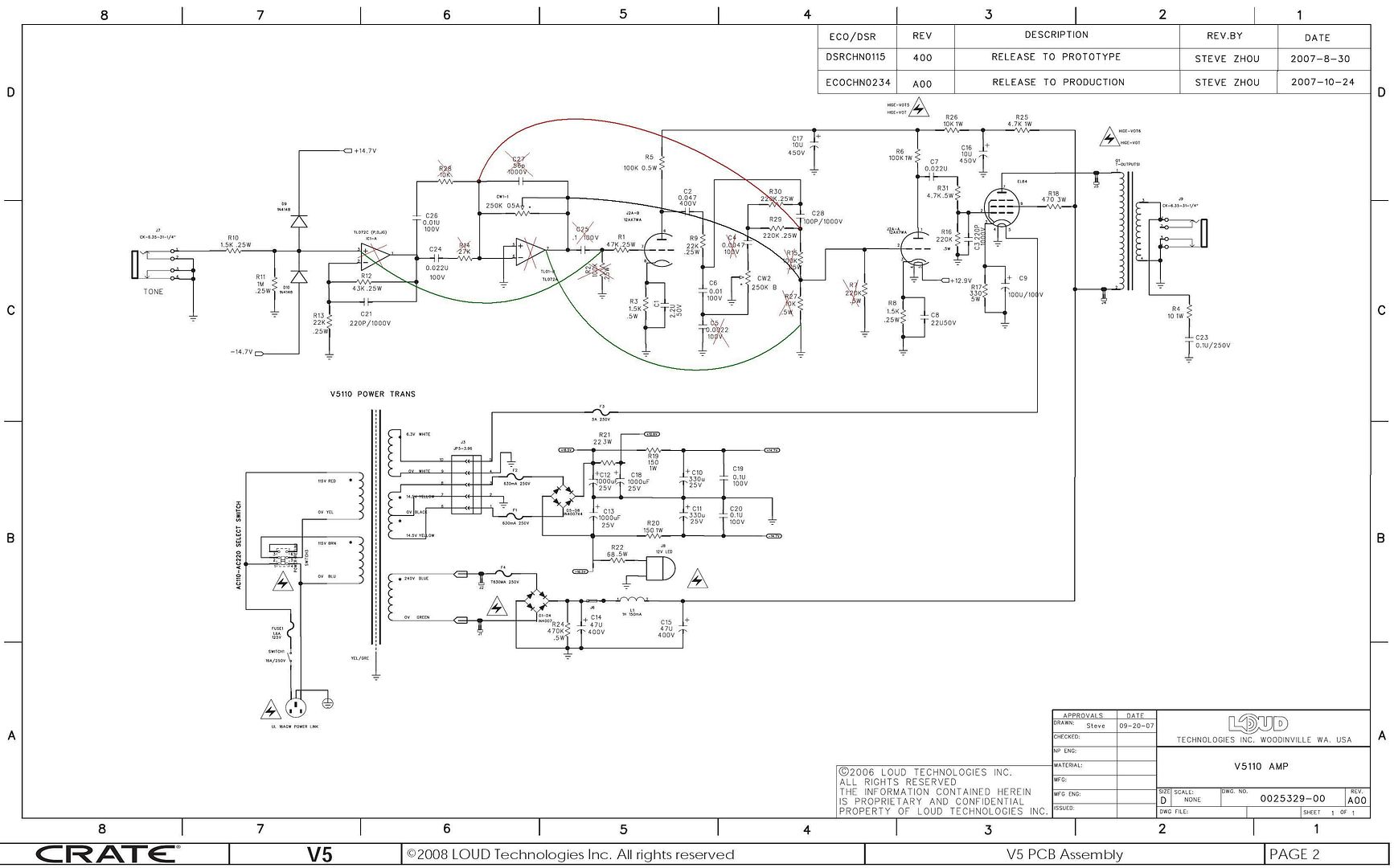
It is the way deafelectroark did it in his mods.

    Quote Originally Posted by jim p
    On to getting more treble by changing C1 do you have two 100 nf (0.1 uf) caps if so two in parallel is equal to 200nf so you could use that at C1 for a treble boost. Just using 100 nf at C1 won’t start to have an effect until 1 kHz so may not be early enough. While 470nf (0.47 uf) will start at 225 Hz which is a little low. Using 200 nf (0.2 uf) the boost will start at 550 Hz. In the case of voltage rating 50 volts is plenty you could get away with 12 volt rating easy.
    You can also put two 470nf caps in series for 235nf that would be close enough to 200nf at C1 location.
    I don't have two of either, I have only one of each. I am curious though, what does the 2.2u C1 stock cap do? Is it more of a mid boost? And, if I use the 100nf will it slightly or greatly increase or boost the treble? I'm just looking for a little more sparkle and not shrill.
    Thanks for the quick response: you rock! :
    Timothy

  15. #243
    Join Date
    Jan 2009
    Posts
    357
    Post Thanks / Like

    Default Re: stock value of C1

    The stock value of 2.2uf for C1 will bypass resistor R3 starting at 50Hz so you get the maximum gain from the first triode minus some 60 Hz (line frequency noise). By going with 200nf the gain is only half (27) for the low frequencies up to about 550 Hz. Then the gain will rise up to the maximum of approx 54. So by changing to 200nf you will drop the gain on the bass to get boost for treble (highs)

  16. #244
    Join Date
    Feb 2009
    Posts
    35
    Post Thanks / Like

    Default

    Quote Originally Posted by timothymegg
    It most definitely works ...
    So maybe the jumper from the volume pot to R27 is not on the ground side of the removed resistor, then it would work as a variable resistor???

  17. #245
    Join Date
    Jan 2009
    Posts
    357
    Post Thanks / Like

    Default Re:how mod works

    Quote Originally Posted by SciHi
    So maybe the jumper from the volume pot to R27 is not on the ground side of the removed resistor, then it would work as a variable resistor???
    I think how his mod works is how I described a similar mod in post #168. The pot is a variable resistor to ground at the control grid of the second triode.

  18. #246
    Join Date
    Aug 2008
    Location
    Honey Brook, PA
    Posts
    25
    Post Thanks / Like

    Default

    Quote Originally Posted by jim p
    Options:
    Remove R7 for higher maximum signal on grid of second triode.
    Short R30 or R29 and remove C28 for more maximum signal at grid of second triode.
    Remove C27 and use the vias (plated holes) in the PCB to connect rheostat (pot) to location of R27. Makes for shorter jumper runs on PCB.
    Replace loss of pre emphasis for tone stack by replacing C1 with a 200nf cap so tone control will be treble boost, flat and treble cut. Or instead change R9 to approx 220k and add a Resistor and capacitor in parallel with it for treble boost.
    I did the no-opamp mod that jim p posted back in post 168 and it was a huge improvement! I also found an old 10" guitar amp speaker of somewhat unknown origin but figured since it had a much larger magnet and was paper instead of plasitic it had to be better and it sure is!

    I didn't do the options jim p posted figuring I wanted a base line sound to compare before making the mods. I have a couple of questions that i hope jim p, or anyone might be able to answer.

    What does "maximum signal at the grid of the second tirode" mentioned in the options to the mod do in terms of volume, overdrive/distortion, etc?

    I use this amp as my living room practice amp so generally the more overdrive/distortion at lower volume the better (within reason). I've wondered if adding another pot to control volume between the second tirode and the EL84 would act as a master volume and allow me to get more distortion at lower volume via preamp overdrive, although preamp overdrive is generally not as smooth as power amp overdrive.

  19. #247
    Join Date
    Jun 2007
    Location
    Westminster, Colorado
    Posts
    2,203
    Post Thanks / Like

    Default

    You might want to check out this blog post:

    http://yeomansinstruments.blogspot.c...hing-ever.html

    The VVR will allow you to dial down the plate voltages to get the power section to overdrive faster and at low volumes. It won't sound exactly like a cranked amp because it isn't pushing air.

    You can buy a VVR PCB from this site:

    http://www.hallamplification.com/main.html?src=%2F#2,2

    tung


    Quote Originally Posted by stoneattic
    I did the no-opamp mod that jim p posted back in post 168 and it was a huge improvement! I also found an old 10" guitar amp speaker of somewhat unknown origin but figured since it had a much larger magnet and was paper instead of plasitic it had to be better and it sure is!

    I didn't do the options jim p posted figuring I wanted a base line sound to compare before making the mods. I have a couple of questions that i hope jim p, or anyone might be able to answer.

    What does "maximum signal at the grid of the second tirode" mentioned in the options to the mod do in terms of volume, overdrive/distortion, etc?

    I use this amp as my living room practice amp so generally the more overdrive/distortion at lower volume the better (within reason). I've wondered if adding another pot to control volume between the second tirode and the EL84 would act as a master volume and allow me to get more distortion at lower volume via preamp overdrive, although preamp overdrive is generally not as smooth as power amp overdrive.

Page 13 of 25 FirstFirst ... 3111213141523 ... LastLast

Posting Permissions

  • You may not post new threads
  • You may not post replies
  • You may not post attachments
  • You may not edit your posts
  •