Warning: preg_replace(): The /e modifier is deprecated, use preg_replace_callback instead in ..../includes/class_bbcode.php on line 2958
Crate V5 mods... anyone? - Page 17
Page 17 of 25 FirstFirst ... 71516171819 ... LastLast
Results 305 to 323 of 465

Thread: Crate V5 mods... anyone?

  1. #305
    Join Date
    Aug 2008
    Location
    Honey Brook, PA
    Posts
    25
    Post Thanks / Like

    Default

    jim_p, after Bill gave me a hard time I finally tried to finish the VVR install and ran into a few questions/issues:

    1) You suggested replacing R26 with a 25K, the closest I could find is 24K. Is that okay?
    2) You suggested replacing R18 with the 4.7K from R25 since R25 is now jumped. R18 is a 3W and R25 is a 1W. That seems like a problem, is it?

    Thanks for your help.
    Last edited by stoneattic; August 20th, 2009 at 08:35 PM. Reason: typos, etc.

  2. #306
    Join Date
    Jan 2009
    Posts
    357
    Post Thanks / Like

    Default Questions on R18 and R26

    The value of R26 is not too critical it is just a series dropping resistor to set the voltage of the plate supply for the 12AX7 so 24k is good. The wattage rating of the R18 resistor with 4.7k max current should be 15mA as the screen grid resistor the steady state current is around 4mA. As the volume out of the amp increases the current through that resistor will rise as a percentage of the plate current I think a 1 watt will be OK but if you have a 2 to 3 watt 4.7k go ahead and use the higher wattage.

  3. #307
    Join Date
    Aug 2008
    Location
    Honey Brook, PA
    Posts
    25
    Post Thanks / Like

    Default

    Thanks again jim_p.

    I would have to order a higher wattage resistor so I'll go ahead and put the 1W in there for now. Next time I'm placing an order I'll pick up a 3W to replace it.

    I'm not going to be playing this amp at high volume anyway. It's meant to be my living room practice amp. I have other amps for loud time.

  4. #308
    Join Date
    Jan 2009
    Posts
    357
    Post Thanks / Like

    Default A different variable voltage regulator

    Thought I would post a different variable voltage regulator that uses two shunt voltage regulators to produce current sources with two n-channel mosfets. The current source at the ground side subtracts current from the high side current source to reduce the current across a resistor attached to the gate of the pass mosfet T2 for voltage regulation. Less current through the resistor R2 equals lower voltage on the output of the regulator. With this the adjustment pot has only 2.5 volts across it instead of over 300 volts so figure this is a little safer. The use of the TL431 ICs as current sources should reduce the ripple voltage of the power supply for a quieter amplifier. Bypass caps can be added to the gate of the pass mosfet T2 in the schematic a 1uf cap is equal to an approx 100 reduction in ripple voltage. The FETs FDP7N50 cost 70 cents each at Mouser and the TL431 goes for 39 cents each.

    There is no current limiting in this circuit with two more resistors and another TL431 a precise current limit could be added.

    Another variable voltage regulator circuit uses zener diodes and the TL431 to control the output voltage of the pass mosfet. The TL431 is used as an adjustable current sink to set the voltage of the output by the voltage dropped across R1. The zener diodes are rated at 5 watts one a 160volt the other a 180 volt other values can be used the value of R2 3.3k may need to be changed if a much lower zener voltage is used.
    Last edited by jim p; August 21st, 2009 at 05:32 PM.

  5. #309
    Join Date
    Jan 2009
    Posts
    357
    Post Thanks / Like

    Default One more regulator circuit

    This is a variable voltage regulator circuit that uses zener diodes and the TL431 to control the output voltage of the pass mosfet. The TL431 is used as an adjustable current sink to set the voltage of the output by the voltage dropped across R1. The zener diodes are rated at 5 watts one a 160volt the other a 180 volt other values can be used the value of R2 3.3k may need to be changed if a much lower zener voltage is used. With this circuit there is just 2.5 volts across the adjustment pot. The current limit is set by the value of R3 the 25 ohm resistor for a limit of 100mA. The current limit can be adjusted with a different value resistor based on the 2.5 volts at the reference pin of the TL431 so 2.5 volts divided by current limit equal to resistor value to use. In simulation I got a ripple rejection ratio of 200 or -46db. On the parts front the FDP7N50 mosfets are 70 cents each at Mouser the TL431 shunt regulator is 30 cents at mouser a 400 volt 1 uf film cap can be used at the gate of the pass mosfet. The current sink mosfet T3 needs no heat sink. If you use a heat sink instead of the chassis for the pass mosfet T2 you will need a 10 C/watt or better heat sink(lower is better say 8C/Watt).
    Using the zener diodes maintains voltage regulation as the raw power supply voltage rises due to lighter current load. Also the adjustment pot has only 2.5 volts across it for a bit better safety. The TL431 provides a precise current limit along with the value of R3 used.
    Of the three circuits this one gives the best ripple rejection so it would probably be the best to use. I would get a few zener diodes to try different total voltage value relative to the raw supply they are around 30 cents each so? Also have added the current limit may want to consider playing with the current limit range so might want to get a few low resistance values if you don’t already have them.
    Last edited by jim p; August 22nd, 2009 at 09:39 AM.

  6. #310
    Join Date
    Jan 2009
    Posts
    357
    Post Thanks / Like

    Default Making an L-pad attenuator look like a speaker

    For those of you thinking about using an L-pad as an attenuator I was looking into how to make the L-pad look more like a speaker to the amplifier. If you look at the impedance curve that you can find at Jensen Speakers or Eminence speakers on the average an 8 ohm speaker looks like approx 6 ohms in series with the average value of an 800uH choke. While an L-pad is two pots one in series with the speaker and one in parallel so it looks like a resistor. With the speaker at approx 800Hz the inductance starts to dominate and the impedance continues to rise to approx 50 ohms at 20 kHz. With the impedance curve you will see a sharp rise in impedance at approx 70 to 110 Hz that is the resonance of the speaker which I cannot duplicate with the L-pad but the high frequency curve can be matched to approx 3 kHz. To do this you need to use an L-pad twice the impedance you want to have for a load so that is 16 ohms for an 8 ohm load and an 8 ohm L-pad for a 4 ohm load. With the 16 ohm L-pad you will need to parallel it with a 12 ohm 10 watt resistor in series with a 1.5mH choke rated for 2 amps then connect the speaker to the normal terminals on the L-pad this looks like an 8 ohm speaker to the amp. The 8 ohm L-pad needs a 5 ohm 10 watt resistor with a 1.5mH 2 amp choke in series in parallel this looks like 4 ohms to the amp. This should get the L-pad sounding closer to speaker at high output levels. I did not look into the resistor price but for the inductor two 820uH chokes in series can be used for the 1.5 mH and they are 2.60 each at Mouser.

  7. #311
    Join Date
    Aug 2008
    Location
    Honey Brook, PA
    Posts
    25
    Post Thanks / Like

    Default

    I finally finished the VVR install and figured I'd give a little update on what I did. The mods I made are:

    1. Removed the IC in the pre-amp and modified the tone control per jim_p's post
    2. Added a Master Volume per jim_p's post
    3. Installed the Hall Amplification VVR to control the voltage to the power tube only (installed it per jim_p's post)
    4. Replaced that abomination of a speaker with a Jensen MOD 10-35.

    The attached pics show:
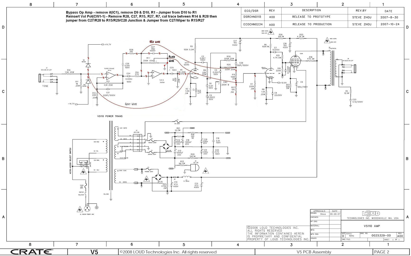
    1. The controls were I installed the Master Volume in place of the original power indicator light and the VVR in place of the original power switch and installed a smaller LED power indicator.
    2. The circuit mods.
    3. Relocating the power switch to the back, underneath (you can see the VVR board as well)

    I made a few mistakes along the way that I had to fix and I'm not proud of the way some of the work looks but the results are amazing. I play a pretty wide range of music, classic rock, 80s, grunge, etc, and I can get plenty of sounds/tones/levels of gain with the mods and additions of the MV and VVR. I can go from pristine clean to a really nice crunch.

    The MOD 10 sounds great. It's really hard to beat for the money (I got it from music123 for $34.80 shipped).

    I couldn't be happier with the way this turned out sound-wise, especially for the money I have into it (about $115 total, including the amp which I picked up used for $40).

    Many thanks to jim_p! :

  8. #312
    Join Date
    Aug 2008
    Location
    Bensalem, Pennsylvania, United States
    Posts
    91
    Post Thanks / Like

    Default

    Sweet!!! Now you can help me with the suggestions Jim gave me for the champion 600.

  9. #313
    Join Date
    Aug 2008
    Location
    Honey Brook, PA
    Posts
    25
    Post Thanks / Like

    Default

    Quote Originally Posted by Bilsdragon
    Sweet!!! Now you can help me with the suggestions Jim gave me for the champion 600.
    Not a chance!!!!


    Just kidding of course, whenever you're ready to go crazy with the soldering iron let me know.

    I'll bring the V5 in on Monday and let you check it out.

  10. #314
    Join Date
    Jan 2009
    Posts
    357
    Post Thanks / Like

    Default An autotransformer volume control with speaker load attenuator

    The autotransformer volume control is a bad thing to connect to a tube amplifier as you lower the volume thus increase the ratio between input from amp and speaker the reflected impedance will rise. These volume controls are fine for a solid state amp that will have problems with low impedance loads but no problem at all with a high impedance load. Most even have the capability to raise the impedance by a factor of two to four for putting speakers in parallel. What happens at a low volume setting it might look like you have 2 k ohms or more connected to the output of the amplifier which might kill the output transformer or power tube on your tube amp. But if we put a simulated speaker load of 6.5 ohms with a 800uH to 2 mH choke in series (equal to an 8 ohm speaker) in parallel with the autotransformer this will be as close to looking like driving a speaker with a roll your own attenuator as you can get. The high reflected impedance of the autotransformer will have little effect on the simulated speaker load so to the amp it will be like driving a speaker.
    If you build this you want to make sure the resistor and inductor load will always be connected when using the autotransformer. You should have the ability to totally by pass it for driving the speaker directly. For the inductance of the speaker load if you use two to three inductors for the maximum value of inductance you can connect switches across then to short them out, with all in being bright to all out being bass or flat in response.
    One thing left out of the simulated load is the resonance response of a speaker this can be simulated with an inductor in parallel with a resistor and capacitor, but fell the low frequency response is not the most important to simulate. Also the resonance is actually the fact that the speaker coil is similar to a motor and a motor can also be a generator. What happens is related to the rebound of the speaker surround and how the speaker is mounted if in an open cabinet, closed back cabinet or ported cabinet as the speaker returns to it natural position it produces a current close to equal to the current needed to produce the tone and amplititude it was driven to. Thus it looks like little current is required to drive the speaker at the resonant frequency so it is a high impedance point in the frequency versus impedance curve.
    For the chokes the J.W. Miller (Bourns) series 2300HT or 2300 have values in the range required and good current capability both Digi-Key and Mouser carry them. The volume controls can be found at Parts Express. For the watt wasting resistor the wattage required should be twice the wattage of the amp you are going to hook up to so for V5 minimum of 10 watts.

    Tried to include a speaker response curve but was cropped down to be of little value.

    Just as a final point on attenuators you are maxing out the output power of the amp so if anything is marginal it might fail with heavy use such as the output transformer. Also your output tube life might be shortened from heavy use. I did see one attenuator that states it is a 30 ohm load and this makes it safer to use but I am not so sure that should be the case. High impedance loads lead to high flyback voltages in the amp which is what causes arc voltages that cause breakdown so not sure this is valid.
    Last edited by jim p; August 29th, 2009 at 04:50 PM.

  11. #315
    Join Date
    Sep 2009
    Posts
    25
    Post Thanks / Like

    Default Help with op amp bypass please

    Hello all....
    Firstly, I am new to the forum and initially came here researching from this thread to mod my v5.
    I mainly play strats and mainly blues and classic rock and was just after a good litle tube amp for practicing at home and hopefully that was loud enought to jam with friends.
    I hope that you aren't all sick to death of going over this now but I am in need of some assistance please.
    My first mod was the speaker - changed to an eminence ragin cajun. Then replaced the the tubes with JJ's. Swapping out the 12ax7 with an at7.
    Before I touched the circuitry the amp didn't sound too bad. It was nice and clear, not overly loud, but it was a little harsh on the highs. Not bad for blues but was enticed into doing the mod given what everyone was saying about the improvement in tone. I also wanted to have a pure tube amp and had not done any mod's to an amp before and figured this was a good place to start.
    So here's where I am at now......
    I read some good reviews of deafelectromarks mod and it seemed easy enough so I followed it as best I could. I am not a tech person but as long as I have instructions I can do most all things. (Modding amps is the next step up for me after building guitars and modding pedals). Given my lack of technical understanding I found the instructions a little vague but think I completed all parts of the mod as indicated.
    My problem is that I don't think I've achieved the results that I think I should have. Main reason being is that I think, if anything, the amp is now quieter (as in less loud) than when I started with very little breakup at full volume. There is no way you could play with a band, even if they played quietly and the amp is on full. I think my little micro cube is louder. I haven't yet touched the tone stack and at the moment it sounds dull and is very much lacking in highs. But my main concern is first getting the op bypass mod right. Though would Jim P's tone stack for op-amp bypass modded circuits work with deafelectro's mod?
    I have attached a pic of both the front and back of the circuit board (no schematic - I'm sure I'd draw it up wrong) for you to see what I have done. So, if you are familiar with this mod or have done it yourself can you please let me know if I have done something wrong.

    These are the instructions I was following:
    *************
    Begin by cutting the trace after the input jack leaving R10,R11 for input loading. This will be just before pin 3 of op amp.
    Run a short length of coax from there to pin 7 of the 12AX7, and ground this wire at only one end (to prevent ground loops).
    You will be cutting the volume pot out of the circuit and reroute wires as follows-keep the tone control circuit for now).
    Connect the middle wiper to pin 2 of 12AX7. Cut out the R7, 220K resistor and the pot will take it's place for the load and volume control BETWEEN the two 12AX7 halves.
    Connect the top of the control to the junction of R15, R29,and C28:
    and the bottom to ground.
    Cut out the 100K (R15) (or R27, 10K) Resistor(s) so that the second half of the preamp tube is driving the same load. So you are basically removing R15, R27 and R7.
    **************
    nb. I removed the op-amp though I know I really didn't need to.
    nb. I used jumper wire instead of co-ax after a later post said it wasn't really required.

    Help please!
    Thanks in advance.
    rhohnj (Ryan)

  12. #316
    Join Date
    Jan 2009
    Posts
    357
    Post Thanks / Like

    Default May be loading down the guitar

    Looking at the picture of the top of the board looks like you may have some parts loading down the input signal. I think you should remove C25 and R1 then you would be better off with the jumper going to the junction of C25 and R2 keeping R1 in series with the control grid. I attached a marked up schematic.
    I don’t like the stock tone control find the dark to bright to dark way it functions to be odd. One problem with taking out the op amp is you have no treble boost without it, so the tone control just becomes a treble cut instead of a boost and treble cut.
    A way to get a boost back is to change C1 to a 220nF capacitor if that is too bright you can split the cathode resistor R3 into two 750 ohm resistors in series with 2.2uf across one resistor and 440nf across the other resistor.
    If you are after maximum volume from the amplifier a 16 ohm speaker is your best choice due to the 20:1 turns ratio of the output transformer.
    Also you may want to go back to a 12AX7 as the preamp tube to see what effect that has.

  13. #317
    Join Date
    Sep 2009
    Posts
    25
    Post Thanks / Like

    Default thanks Jim

    thanks Jim
    I will try this and see how I go but if anyone else has other views I'd still love to hear their thoughts too.
    Though I will stick with the current 8ohm speaker given I just bought it.
    Your previous posts and this response is much appreciated.
    cheers
    Ryan

  14. #318
    Join Date
    Sep 2009
    Posts
    25
    Post Thanks / Like

    Default query on your mod pics

    Quote Originally Posted by timothymegg
    Ok, I got some pictures of deafelectromark's mod and so, I think I finally have it how he did the mod on the schematic and his pictures of the board.


    Hi Tim
    Looking at your pics there seems to be some parts removed not detailed in deafelectro's mod instructions. (D9, D10, R28, R1, C27) and also cut the trace between R28 and R29.
    Is this something youcame up with yourself? What effect did it have?
    cheers
    Ryan

  15. #319
    Join Date
    Jan 2009
    Posts
    357
    Post Thanks / Like

    Default error on schematic for mods

    There is a cut needed not shown in the schematic above. You need to cut the wiper of the pot free from ground. I think this has come up before.

  16. #320
    Join Date
    Sep 2009
    Posts
    25
    Post Thanks / Like

    Default next steps?

    Quote Originally Posted by jim p
    Looking at the picture of the top of the board looks like you may have some parts loading down the input signal. I think you should remove C25 and R1 then you would be better off with the jumper going to the junction of C25 and R2 keeping R1 in series with the control grid. I attached a marked up schematic.
    I don’t like the stock tone control find the dark to bright to dark way it functions to be odd. One problem with taking out the op amp is you have no treble boost without it, so the tone control just becomes a treble cut instead of a boost and treble cut.
    A way to get a boost back is to change C1 to a 220nF capacitor if that is too bright you can split the cathode resistor R3 into two 750 ohm resistors in series with 2.2uf across one resistor and 440nf across the other resistor.
    If you are after maximum volume from the amplifier a 16 ohm speaker is your best choice due to the 20:1 turns ratio of the output transformer.
    Also you may want to go back to a 12AX7 as the preamp tube to see what effect that has.
    Hi again Jim - sorry, hope you're not sick of me yet.... just want to clarify a couple of things.
    I performed the simple mod you suggested, pulling out R2 and C25 and moving the jumper to between them. Well I definitely got an increase in output volume (and tube break-up) - thanks again!
    I haven't yet boosted the treble as I need to get to the store to get a 220nf capacitor.
    So.... I am hoping, but don't know yet, if that will fix my current problem which is that it gets very 'farty' when you plug in humbuckers. It's not too bad with single coils (but has lost the tightness in the bottom end I had pre-mod) - do you think the 'fartiness' will go away with an increase in the treble from the change in cap at C1? Or do I need to modify something else?

    Also, you were nice enough to mark up a correct shematic (in last post) for the similar, but more extensive mod that Timothymegg originally posted. This mod had further components and traces removed. Do you know if that would yield a different result to what I currently have? What are those extra pieces doing (R1, D9, D10, R28, C27)? Just in case it helps I wouldn't mind getting back a little bit of fender into this amp that has quickly turned very marshall-ish.

    On another note... I just pulled apart an old 70's 70watt hi-fi amp for parts. It's got a nice big sansui power transformer. How do you think this would go if I used it in a guitar amp???

    thanks!!!!

    Ryan

  17. #321
    Join Date
    Jan 2009
    Posts
    357
    Post Thanks / Like

    Default The other parts

    Removing D9 and D10 will make no real difference they were in there to protect the op amp but have no real effect on the input signal. Having R1 in series with the control grid of the tube will help roll off high frequencies when you overdrive the input tube and help keep radio interference down. Taking out R28 and C57 may take them out of circuit with the volume pot mod so probably a good thing to do.
    For more of a Fender tone should consider adding feedback look through the previous posts and you should find it as a mod already described.
    If it is a 70 watt solid state transformer it would only be useful for a 70 watt state amp, probably good for plus and minus 40 to 45 volt supplies so of no use with tubes.

    On the feedback look at the post "Adding a presence control (feedback) to the V5"
    Last edited by jim p; September 23rd, 2009 at 11:05 AM.

  18. #322
    Join Date
    Jan 2009
    Posts
    357
    Post Thanks / Like

    Default tube bias and tone

    This is a good article on cathode biasing and setting up the DC bias for the tone you want. http://www.freewebs.com/valvewizard1...Gain_Stage.pdf
    For the most part it is how the tube responds to overdrive so the tube to play with would be the second triode on an amp with the master volume mod. I have posted a schematic that uses mosfets to parallel the highest bias resistor value to set the DC bias for different tones. The first bias rock will have the tube cold biased so it will clip at cutoff (no current flow). Pulling in the first switch Jazz will center bias the tube for the most head room so not intended for clipping. The second switch Blues will hot bias the tube so it will clip at saturation where the control grid starts to conduct. The mosfets can be turned on by the DC heater voltage and will keep the ground loop close to the tube for minimum noise. You can also just go with a fixed bias equal to 10k to 5k for Rock, 2.2k to 1.2k for Jazz and 750 to 500 ohms for Blues bias.
    Also attached a load line equal to 100k plate resistor with 250 volt plate supply to show where some of these bias values fall on the load line.

  19. #323
    Join Date
    Sep 2009
    Posts
    25
    Post Thanks / Like

    Default

    Quote Originally Posted by jim p
    This is a good article on cathode biasing and setting up the DC bias for the tone you want. http://www.freewebs.com/valvewizard1...Gain_Stage.pdf
    For the most part it is how the tube responds to overdrive so the tube to play with would be the second triode on an amp with the master volume mod. I have posted a schematic that uses mosfets to parallel the highest bias resistor value to set the DC bias for different tones. The first bias rock will have the tube cold biased so it will clip at cutoff (no current flow). Pulling in the first switch Jazz will center bias the tube for the most head room so not intended for clipping. The second switch Blues will hot bias the tube so it will clip at saturation where the control grid starts to conduct. The mosfets can be turned on by the DC heater voltage and will keep the ground loop close to the tube for minimum noise. You can also just go with a fixed bias equal to 10k to 5k for Rock, 2.2k to 1.2k for Jazz and 750 to 500 ohms for Blues bias.
    Also attached a load line equal to 100k plate resistor with 250 volt plate supply to show where some of these bias values fall on the load line.
    Wow.. I think you read my mind. I was researching biasing throughout this thread last night.
    I have done all of my modding except for the bias which causes me some clipping from when the amp is cranked and heavily over driven.
    My other mods have left my amp sounding awesome. Thanks again for your assistance.
    After my initial low volume problem, as recommended, I have since removed C25, R2, put back in R1 and jumped to R2, C25 junction - solved volume problem. Then removed D9, D10, R28 and C27, cut C14/C28 trace and swapped out C1 for a 470nf. I didn't have a 220nf, but it sounded great so I kept it. Then after pulling out C5 I got a little more sparkle. The wiring is now all much neater and the sounds is truly great - no need for the feedback mod, I got back all the crystal clear top end that I was after.

    So now I am thinking I might just put in a master volume and definitely need to do something about the bias. I still need to do some homework on this to understand the theory better but do i need to first tackle the screen grid voltage or do I just need to worry about finding the right resistor to add in parrallel with the already existing 330ohm R17? (I have a 12AT7 in there).
    And does the added resistor in parrallel need to be 2 watt or great if added in parrallel given there is already a 5 watter in there?

    And not than I am not happy because this is just a little 5 watt, 10inch practice amp but is there a way to thicken up the bottom end a little?

    Ryan

Page 17 of 25 FirstFirst ... 71516171819 ... LastLast

Posting Permissions

  • You may not post new threads
  • You may not post replies
  • You may not post attachments
  • You may not edit your posts
  •