Warning: preg_replace(): The /e modifier is deprecated, use preg_replace_callback instead in ..../includes/class_bbcode.php on line 2958 The .45 is Alive! (or how to build your own tube amp in seventy billion steps.)
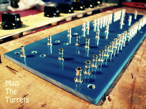
So I decided on copying the original JTM45 as the circuit for the rebuild and set about ordering piles of parts. I chose from the usual suspects for this kind of project, Replica transformers from Marstran, turret board from Watts Tube Audio, Sprague, Sozo and F&T caps, alpha pots and so on. I even used vintage style cloth covered wire throughout (not because I think it sounds better, because it looks amazingly cool, eliminates wire stripping, and stays in place very nicely.)
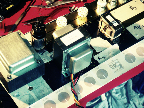
Once parts started to arrive the challenges started to become apparent. Here's some of the fun and excitement that occurred when I started mocking things up.
The Vase chassis is mounted upside down compared to a Marshall so all my controls are reversed.
The Vase chassis had the output tranny, inputs, cap cans, controls, and inputs all in different places to the Marshall
The KT66's are much bigger than 6L6's, so late in the piece I discovered if I mounted the power tubes "conventionally", the chassis would not fit back in the shell. (this was a considerable challenge)
The rear of a JTM chassis is completely exposed, so plenty of room for the traditional captured power cord, two speaker jacks, a fuse and an impedance switch. The back panel of the Vase covers 2/3 of the available real estate, so I had to cram.
So first things first, here's how it all went down.
I started out just visually laying out how all the big components would be laid out. I wanted to keep it as close to the original design to minimize hum and oscillation issues.
Initially I was super impressed with the turret board, but the way they shrunk it to accommodate modern resistors actually made the layout quite cramped and tricky in places.
So while I was waiting for parts and working out where all the bits would fit, I made some calls on design.
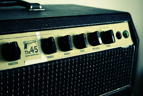
I decided to keep the original (now "Vintage") red and green indicator lamps and the rotary power switch as a nod to the original Vase. Also retained was the chassis (although massively modified) and of course it's going back in the original head shell.
I decided to use a nice modern IEC style power socket with integrated mains fuse. It saved me space on the back panel by not needed a separate mains fuse and when it comes to power, old school 'capture' cords can stay in the 60's.
The only other change from "original" JTM45 spec is that I've left out the "flying" resistor, rotated the power transformer 90 degrees (so I didn't have to cut out a different hole) and whilst not connected yet, it'll have a Lar/Mar style PPIV MV. I've also top mounted both cap cans instead of just one.
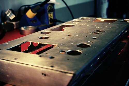
So with the decision made to replicate the JTM as closely as practical, I had to get cutting, and filing, and sanding, and cutting, and more filing, and a bunch of drilling, then more filing and, well you get the picture.
Because every single component, with the exception of the power transformer, was going to have to be mounted in a different place, I had to take a chassis that had already been drilled and filed for two amp designs, and make it ready for a third. As you probably realize, you can take aluminium away from a chassis, but you can't easily add it back. Luckily, I managed to score a huge section of gold anodized aluminium from a local scrap guy which was a massive score as it looks like brass and cost $2 !! I made the front and rear panels out of it as well as all the sections that look "brass like" in the pictures.
I made a section for mounting the three 12AX7's, a blank plate to cover the original "drop through" output tranny, and most significantly, the mounting tray for the power tubes, but I'll come back to that.
Oh, I almost forgot. I absolutely wanted to maintain the "four hole" layout the Plexi amps were famous for. Great in theory, but the Vase chassis has it's control plate at a 45 degree angle, not 90 like a Marshall, so I had to get all choppy to fit all four sockets in there.
The hardest bit though was fitting those monster KT66's in. I mentioned before that I discovered late in the design how massive they were, but luckily I was still in the metalwork phase so whilst annoying and time consuming, it could have been worse. I could have discovered it after wiring it all up.....
Here's where I get a bit McGuyver.
For the KT66's to fit, I had to drop them 20mm down into the chassis. That meant fabricating a mounting plate, installing steel standoffs, fabricating a cover plate (with massive holes in it, those KT's are FAT man) and relocating the speaker outputs further away from the impedance switch than I'd have preferred.
It was quite a mission getting everything to line up the way I wanted for the custom power tube mount I can tell ya. I built this entire thing on a little table in my dining room with basic tools. No workshops were harmed in this project
So they were the basic design considerations and biggest challenges. On to part 3


 Reply With Quote