Post #16
After the input resistors (1.5Kohm and 1 Meg) I cut that trace going to the input of the op amp and sent it straight to the first tube grid and cut away any other parts that were there that might have influence. Since I now had a 250Kohm volume pot out of the circuit, I put that between the tone circuits and the grid to the second triode in place of the attenuation scheme that was there and to maintain grid to ground loading and control. I cut the traces around the volume pot and ran jumpers to the appropriate places (the pot connects to the output of the tone circuit, the two lower resistors were cut out, and the other end of the pot was run to ground. The wiper fed the second triode's grid.
Deafelectromark (alias manoteal)

Post #97
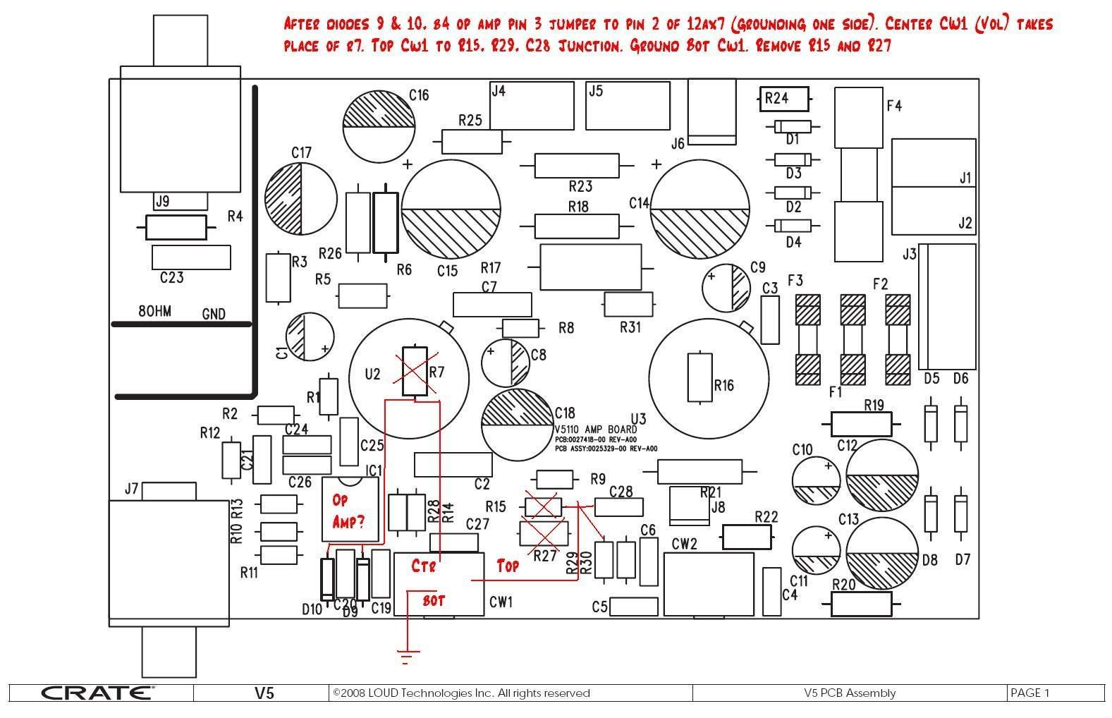
Begin by cutting the trace after the input jack leaving R10,R11 for input loading. This will be just before pin 3 of op amp. Run a short length of coax from there to pin 2 of the 12AX7, and ground this wire at only one end (to prevent ground loops).
You will be cutting the volume pot out of the circuit and reroute wires as follows-keep the tone control circuit for now).
Connect the middle wiper to pin 2 of 12AX7. Cut out the R7, 220K resistor and the pot will take it's place for the load and volume control BETWEEN the two 12AX7 halves (this is so your guitar and/or you stompbox can play clean into the preamp tube or to push it more into output stage distortion)
Connect the top of the control to the junction of R15, R29,and C28: and the bottom to ground. Cut out the 100K (R15) (or R27, 10K) Resistor(s) so that the second half of the preamp tube is driving the same load. So you are basically removing R15, R27 and R7.


Timothy
Originally Posted by deafelectromark


 Reply With Quote