

I heard a crate with the warehouse spkr greenback clone($69-green beret) in it and it made a world of difference.,,well worth the expense
edit* my bad, that was a 12"

 Regular Fretter

I heard a crate with the warehouse spkr greenback clone($69-green beret) in it and it made a world of difference.,,well worth the expense
edit* my bad, that was a 12"
guitars-esp m1,esp vintage plus strat,85 gibson LP std,Hamer std,hagstrom xl-5,takamine 330r
amps-egnater tweaker,epi vj w/brat mod
efx-byoc/dvm comp, j cantrell wah,ocd,catalinbread dls,wampler plextortion,ibanez chorus,tech21 boost dla
Super Duper Fretter
Warehouse makes a 10" speaker as well:Originally Posted by Andy
http://warehousespeakers.com/products.php?cat=8
Probably better sounding than the stock speaker.
I really hate to recommend this one but for an inexpensive, good sounding OT, Edcor USA makes a decent one. I hate to recommend it because it comes with faston solder tabs. It looks identical to the one here:
http://www.diycustomamps.com/images/...chassis_57.jpg
These are inherently unsafe as there is exposed B+ outside the chassis, not a good idea. If you decide to use one of these, be very careful and insulate all the solder tabs. Don't touch the OT with the amp on. They're about $20US + shipping.
tung
- Dave Lizewski, Kick-A$$I was just a regular guy. My only super power was being invisible to girls.
Regular Fretter
I bought one of these after I sold my perfectly modified Epiphone Valve Junior with the help of 18watt members and 300+ pages of chit-chat. I get bored rather easy, and was going to go with the Valve Junior again (I sold it to see if I could get the combo and do similar things, but the price increase told me that there were greener pastures) as a platform, but decided to try out the Crate V5 since it was a combo not much bigger than the VJ. I like 10 inch speakers, I liked the looks of the amp, and thought that even if I have to replace everything and even make up a tagboard for it, it would still be cool. I also was hearing what others have been saying about the Crate and when I got it, surprise! I agreed that there was something amiss and decided that to just accept it and give it back would be like throwing in the towel. I knew that it could be better and I systematically worked on each section to see how my $100 initial investment could be improved on.
Speaker was pulled first. Weighing about a pound and with a tiny magnet, tiny voice coil, stiff suspension and a plastic (!?) cone, I could tell just by tapping on it that this was a tone sucker and big part of the bass weakness. I figured that it could be used in an amplifier to take to the beach or other dirty, wet place. The chassis looked awfully close to the speaker magnet, and I didn't think I could get anything in there that would be decent.I measured the depth of other speakers that I had and found that I was wrong. There WAS room for a better speaker. I popped in a 50 watt Eminence 10 inch and it cleared the chassis. Hooked it up and fired it up- better tone and bass, but the amp was still shrill and unmusical.
Looking inside the amp on the circuitboard I saw of all horrors, an op amp!. OK, I know, you can get good sound out of op amps, but looking at the circuit with the volume control in the feedback loop in the second stage, was didn't sit right with me. After the op amp, the tube circuit was fairly conventional other than a quasi- parametric tone circuit between two tube sections of the 12AX7. But looking at the output of the second triode section, I could see that 90% of the signal was dumped just before it got to the grid of the power tube. I guess that is why they needed the op amp in there- to make up for lost gain in the output tube's voltage divider at the grid. (Why?)
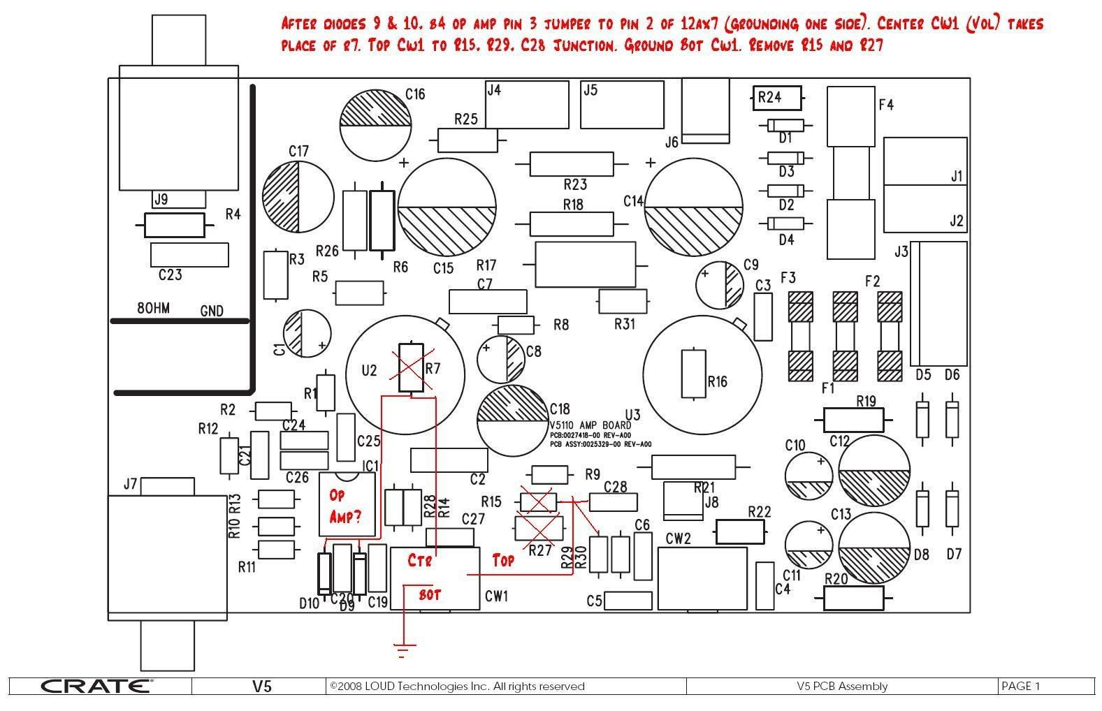
So what I did is to cut some traces and add some jumpers to make it an all tube amp. After the input resistors (1.5Kohm and 1 Meg) I cut that trace going to the input of the op amp and sent it straight to the first tube grid and cut away any other parts that were there that might have influence. I decided that the tone control was not a bad thing, just different- and I left it as is. Since I now had a 250Kohm volume pot out of the circuit, I put that between the tone circuits and the grid to the second triode in place of the attenuation scheme that was there and to maintain grid to ground loading and control. I cut the traces around the volume pot and ran jumpers to the appropriate places (the pot connects to the output of the tone circuit, the two lower resistors were cut out, and the other end of the pot was run to ground. The wiper fed the second triode's grid.
I checked for stability (good) output power-6.1 watts at clipping; up to 9 watts fully overdriven. and residual noise 7mV rms (from the power supply). The tone control can be more easily understood when you use a fuzz pedal or other distortion box into the input. It changes the midrange tone in weird ways, but it is better than just a treble cut, since your guitar already has that. Put your metal pedal in front of it and see how much range of tones you can get from it.
Clean on this amp is very good. You can have your amp set at 12 noon, and your guitar all the way up and it will be clean until you start hitting notes hard (or if you have hotter pickups, perhaps a bit sooner. Alternately, you can turn the amp all the way up and still get clean tones with the guitar just cracked open and swell into the realm of output tube distortion. It is very easy on the ears and very pedal friendly. Using external EQ helps you get the tone that you need/want from various axes.
I had ordered a new transformer for this amp (EDCOR 15 watt- the same one I used in my Valve Junior with great success- $20.64 plus $6.37 shipping), but I am happy enough with it the way it is (the output transformer in the Crate is much bigger than the Valve Juniors'- 10 watts instead of 5). I get deep tone from only a 10 inch speaker and I have to be careful not to use the neck pickup too much- it rattles the pictures and things on the wall in the living room. That transformer is going to have to wait for my 6550 single-ended project. One big output tube- should be cool and about 10 watts!
If you just want to add lots of gain easily and just get your feet wet in trying things, pull out resistor R27 (10K) and short out R 15 (100K) and that will get all the lost voltage (the sound) to the output tube and not lost in those 2 resistors. That way you still have the 2-stage op amp pre driver and it might be more of what you want (if more is better- like metal tone). I wanted pure tube and I got it with only an Exacto knife, 3 pieces of short wire, and some cutters and soldering rig, I didn't need to replace the output transformer, or add any parts in any location. Other than replacing the speaker, that was my only expense. I got the 50 watt Eminence for $12.00 each when I bought 4 from a music outlet store on line. I have used those speakers in amps from this 5 watt one to a stereo 15 watt rig and for a 40 watt combo as well. Tubes are all stock. Surely a better transformer and/or tubes will make a difference, but I got night and day difference with these simple mods. Sounds great for little $$$. If you want, and you can pull the board and replace it yourself, I can mod it for anyone for $40.00 plus shipping (which would be nominal in a Priority mail flat rate envelope ($5.00). There is hope for Crate V5 to become the 'next big thing in small amps.
Deafelectromark (alias manoteal)
Regular Fretter
Curious what Eminence speaker you used that actually cleared the chassis? It's a tight squeeze in there.
I really love the cleans on this amp.
Regular Fretter
I used a 50 watt, 4 ohm Eminence that had a height of 3 1/2 inches, which is the same for most Fender Custom-made, 10" speakers. The original speaker is 3 3/4", so they both cleared easily. The actual opening depth before you hit the chassis is 4 1/4 inches. A friend wanted a Kustom, 50 watt, 8 ohm and 10 inch speaker and I decided to put it in my amp to see if it was clear. Well the speaker looks to be 4 1/4 measuring it out of the cab, and I popped it in and then bolted down the chassis screws and it felt like it WAS touching the chassis. But then I pushed down a little with my hands and found that the magnet was filling the gap due to it powerful magnet strength. I wedged in some credit cars to measure the gap and it came out to be 0.10 clearance (1/10th of an inch!) with 3 credit cards fitting in, and so I thought it was doable. So I pulled the amp out again and bolted the speaker to the proper torque, and put the amp back in again. But now the clearance was 0.20- twice as much. That was due to the speaker's cardboard mounting material being squished a bit by being bolted down.
There may be variations for this useful measurement, but I am convinced that any 10 inch speaker with a thickness of 4.05 to 4.15 will be able fit with at least 0.10 clearance between the amp chassis and speaker magnet. The Kustom sounds great and produces over 100dB with 5 watts input. Nice, no-shrilly tone and very good low extension, too.
I have two orders on the board mod I am doing to return it to a basically all-tube amp. I hope that their ears as as pleased as mine- I play this guy everyday and have no complaints. Wait and see their impressions after I send them back their modded boards.
Mark
I really love the cleans on this amp.[/QUOTE]
Last edited by deafelectromark; March 27th, 2009 at 05:52 PM.
Regular Fretter
[/QUOTE]
I used your post. I removed the chassis and pressed down hard on the speaker while tightening the screws down hard. Then(fighting the magnet)I repositioned the chassis and pulled it away from the speaker while tightening those screws. I did it...I got clearance...may only be .10" but it is definitely no longer touching and that speaker is definitely 4". My cabinet wouldn't take anything larger unless I opened the chassis screw holes larger. I'm happy because I really like the Warehouse speaker. It was a pain in the *** for sure...it's hard to be that firm and be careful at the same time, but I did it. No damage I can see...or hear...sounds great. Thanks for the post!:
Regular Fretter
The first stage op amp is not a tube screamer it is an overdrive stage for the first triode. I have seen some postings for the V5 and its father the VC508 calling the first stage a tube screamer it is not. The VC508 has problems in that the op amp has only +/- 7 volt supplies while the V5 has +/- 15 volt supplies so you should not run into the rails (op amp clipping) with the V5. If you are worried about the supply limits R19 and R20 can be lowered in value to raise the rails to +/- 18 volts for more headroom. A tube screamer is an op amp with two diodes in the feedback to cause clipping which is a poor mans version of what a tube will do. Also the choice of op amp in a tube screamer is based on the op amp recovery time from clipping which should never occur in the V5. Changing the op amp in this amplifier to a JRC4558 would be a bad idea because its low input impedance will kill your highs from the guitar (plus the over all spec for the TL072 is better in noise and input impedance it is a fet op amp not a bipolar). The classic Ibanez tube screamer is a 250k load on your guitar while most of you tube types like the idea of 1 Meg to keep the highs. If you like the sound of a tube screamer fine but it is trying to simulate what an overdriven tube will do and you have a tube to overdrive so no reason to use it. If you want to overdrive a tube amp using an Ibanez tube screamer is not the way to do it, you want to up the signal level into the amplifier without clipping so the tube in the amp will clip.
Of course you need to get a volume control between the first and second triodes in the V5 to use the op amp as an overdrive if not it is just a volume control. So you will have a solid state preamp with tube output .
Regular Fretter
I looked the mod deafelectromark (manoteal) posted with the schematic and, I think there is a discrepancy? In post 16 talk about the jumper from before the op amp to the first triode stage. In post #97 the actual pin number of the jumper is mentioned as pin 2. Looking at the schematic, if it was jumped to pin 2 then there would be nothing connected to pin 7 of the preamp tube. My guess is that the actual connection should be to pin 7? There is also mention of grounding one end of the coax... is that just the shielding or the core too?
I have no electrical experience so I am asking the people who are in the know to help on this one.Timothy
PS: below is deafelectromark's posts that apply here. I have also tried to link the schematic with my best guess of the mod.
Regular Fretter
[QUOTE=timothymegg]I looked the mod deafelectromark (manoteal) posted with the schematic and, I think there is a discrepancy? In post 16 talk about the jumper from before the op amp to the first triode stage. In post #97 the actual pin number of the jumper is mentioned as pin 2. Looking at the schematic, if it was jumped to pin 2 then there would be nothing connected to pin 7 of the preamp tube. My guess is that the actual connection should be to pin 7? There is also mention of grounding one end of the coax... is that just the shielding or the core too?
I have no electrical experience so I am asking the people who are in the know to help on this one.
PS: below is deafelectromark's posts that apply here. I have also tried to link the schematic with my best guess of the mod.
You are right.: The second half of the preamp tube's input is pin 2 on the schematic and not pin 7. Pin 7 is the input to the first half of the triode (from the guitar jack and as shown in the schematic). I will have to pull my board and look at it again to see what I did. Sometimes I think that lower numbers come first (hence the confusion about pin 2 and 7) Remember that tubes pins are clockwise from the bottom after the space and not from the top- I made this transcription error late at night and pretty groggy. My apologies to all that have tried this and it didn't work for them.
I will double check my work (three happy customers right now for the boards that I made for them), so I just made a mistake in that post. I will post again with the right information.
In reference to shielded wire (coax), the coax is not really needed (I didn't have problems with it or without it- it is such a short run) but if you do use coax only ground one end of it (I prefer the input side coming from the input jack ground) for reduced ground loop problems. The middle conductor (not the braid, is for running a connection past the opamp to the input pin of the tube's first section (pin 7). It is always the braided part that is connected to ground (at only one end).
Does that make sense?
Thanks for catching that Timothy. I was just seeing if anyone was awake!
Mark
Last edited by deafelectromark; May 13th, 2009 at 12:49 PM. Reason: spelling
Regular Fretter
I haven't done the v5 mod, but I think you want to either cut the trace after R11 before the diodes, or pull R10 leg and move R11 up front where it should be and connect from R10 leg to the tube input. If you pull R1, then you would just run the jumper to the tube side R1 hole. (maybe these pictures will work? WOW, guess I got carried away in making them small, maybe better now...)
http://i615.photobucket.com/albums/t...pampbypass.jpg
http://i615.photobucket.com/albums/t...nputreturn.jpg
Last edited by SciHi; May 14th, 2009 at 05:43 PM.
Regular Fretter
Ok, I got some pictures of deafelectromark's mod and so, I think I finally have it how he did the mod on the schematic and his pictures of the board.
Regular Fretter
Hi Tim
Looking at your pics there seems to be some parts removed not detailed in deafelectro's mod instructions. (D9, D10, R28, R1, C27) and also cut the trace between R28 and R29.
Is this something youcame up with yourself? What effect did it have?
cheers
Ryan
Regular Fretter
I'm curious why R11 should be upfront? What does that do? and what does having the way it is change anything?
Regular Fretter
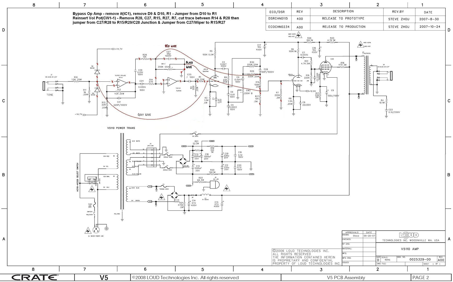
Caution the schematic mark up of the volume pot in post #207 is wrong. Where it shows the red wire connected on the pot should be where the pot should be grounded. Then the red wire should be connected on the side of the pot that used to be connected to pin 7 of the op amp. The little dot on the schematic symbol is probably indication of clock wise direction so at full clock wise you want the wiper of the pot at the R29 side(when mod completed). There is also a cut not shown on the schematic the wiper needs to be cut free from the other terminal of the pot. If you leave R1 in this will give you some feedback for high frequencies on the input triode and if over driving the input to amp sounded shrill it would give a plate to grid feedback cap something to work against. The diodes are a few Pico farads the guitar cable is more capacitance then they are so no big need to remove them they were in there to protect the op amp input so your choice. The location of the 1 Meg to ground is not that critical the difference in distance is what an inch or so this is inside of a shielded enclosure and these are audio frequencies. If you remove the op amp C25 and R2 all you need to do is run a jumper from the feedthrough hole of pin 3 of the op amp to feedthrough hole of C25 or R2 to connect input signal to first stage.
Regular Fretter
[QUOTE=So what I did is to cut some traces and add some jumpers to make it an all tube amp. After the input resistors (1.5Kohm and 1 Meg) I cut that trace going to the input of the op amp and sent it straight to the first tube grid and cut away any other parts that were there that might have influence. I decided that the tone control was not a bad thing, just different- and I left it as is. Since I now had a 250Kohm volume pot out of the circuit, I put that between the tone circuits and the grid to the second triode in place of the attenuation scheme that was there and to maintain grid to ground loading and control. I cut the traces around the volume pot and ran jumpers to the appropriate places (the pot connects to the output of the tone circuit, the two lower resistors were cut out, and the other end of the pot was run to ground. The wiper fed the second triode's grid.
Deafelectromark (alias manoteal)
So, I love the ideas presented here, and I know it's been a while since you posted this, but is there any chance you have a better schematic with illustrations or notes added, and/or gut shots of the mods as described? I may try the easy mods you suggest first and replace the speaker, but this sounds like it might be easier than getting or making a tweed princeton clone out of the little bugger. Not that there's anything *wrong* with that, just typing it makes me think 't was a good plan, don't give up on it now...
Anyway, any hints or tips you'd care to share would be greatly appreciated.
Thanks!
Edit: Noob mistake. Epic fail?! I only just noticed that there's like 24 pages to this thread going right up to the present day and I may need extensive review of the other 23 pages before I start cutting traces. But I might anyway. We'll see...
Regular Fretter
Here is a schematic of the modification I discussed above, it's similar to Deafelectromark's mod except I wanted to re-voice the preamp, replace the tone control with a mid-cut tone control and instead of cutting the traces to the volume pot I pulled it from the pcb (be careful if you aren't familiar with pulling components or you'll end up with a damaged pcb)
http://rh-tech.org/public/Crate_v5_Framing-Leah.jpeg
If you want to keep the stock tone control only remove R15, R27 and R7 (I just cut R7 out) from between the two stages. The volume control input (clockwise lug) connects to R15 where it connects to R29, the volume control wiper connects to R15/R27 junction, the volume control ground connects to the ground via on R27.
Posting Permissions

 Reply With Quote

